
Method for the graphical representation of a medical instrument inserted at least partially into an object under examination

a medical instrument and graphical representation technology, applied in the field of graphical representation of a medical instrument inserted at least partially into an object under examination, can solve the problems of reducing the subsequent image processing outlay and therefore computing time, and achieve the effects of improving patient safety, facilitating medical personnel to plan, and increasing the contrast of the environmen

Active Publication Date: 2010-03-16
SIEMENS HEALTHCARE GMBH
View PDF22 Cites 56 Cited by
  • Summary
  • Abstract
  • Description
  • Claims
  • Application Information

AI Technical Summary

Benefits of technology

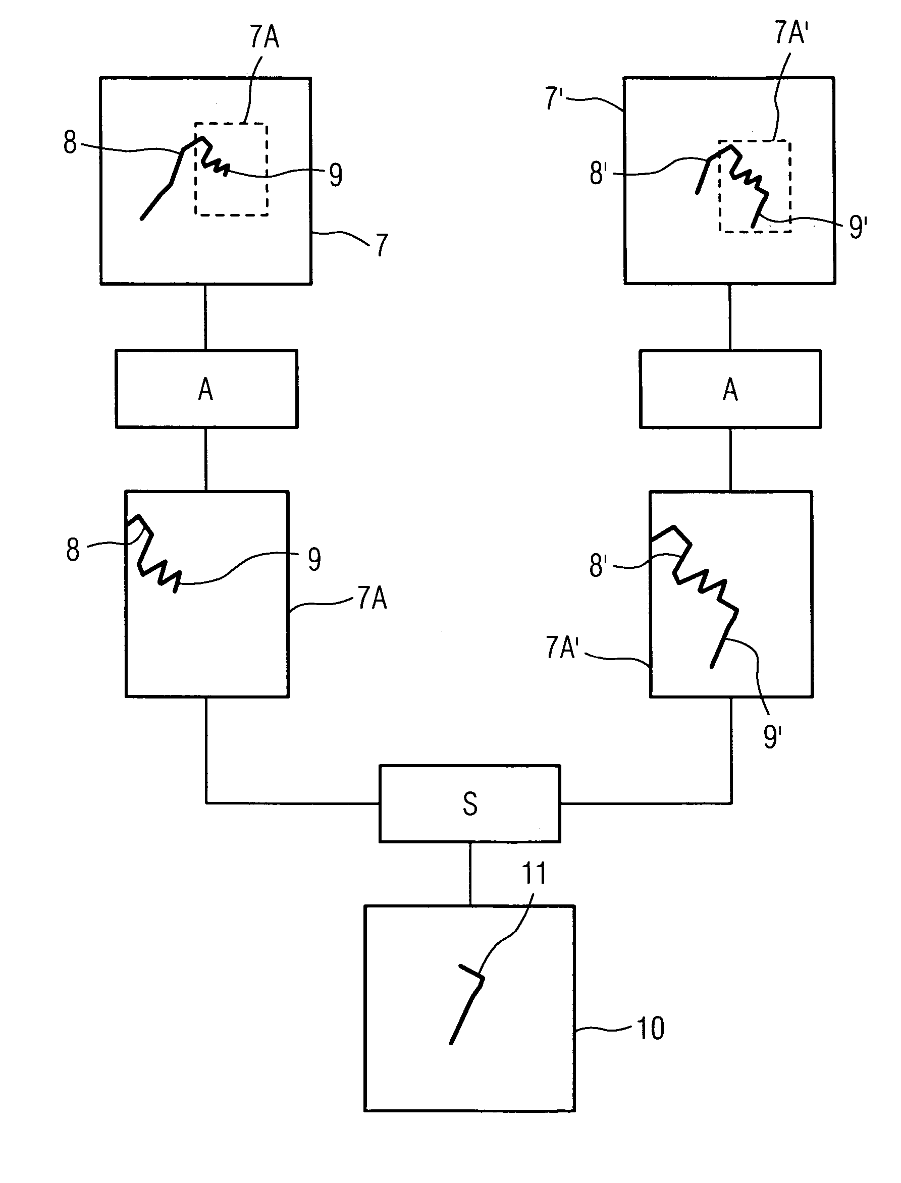
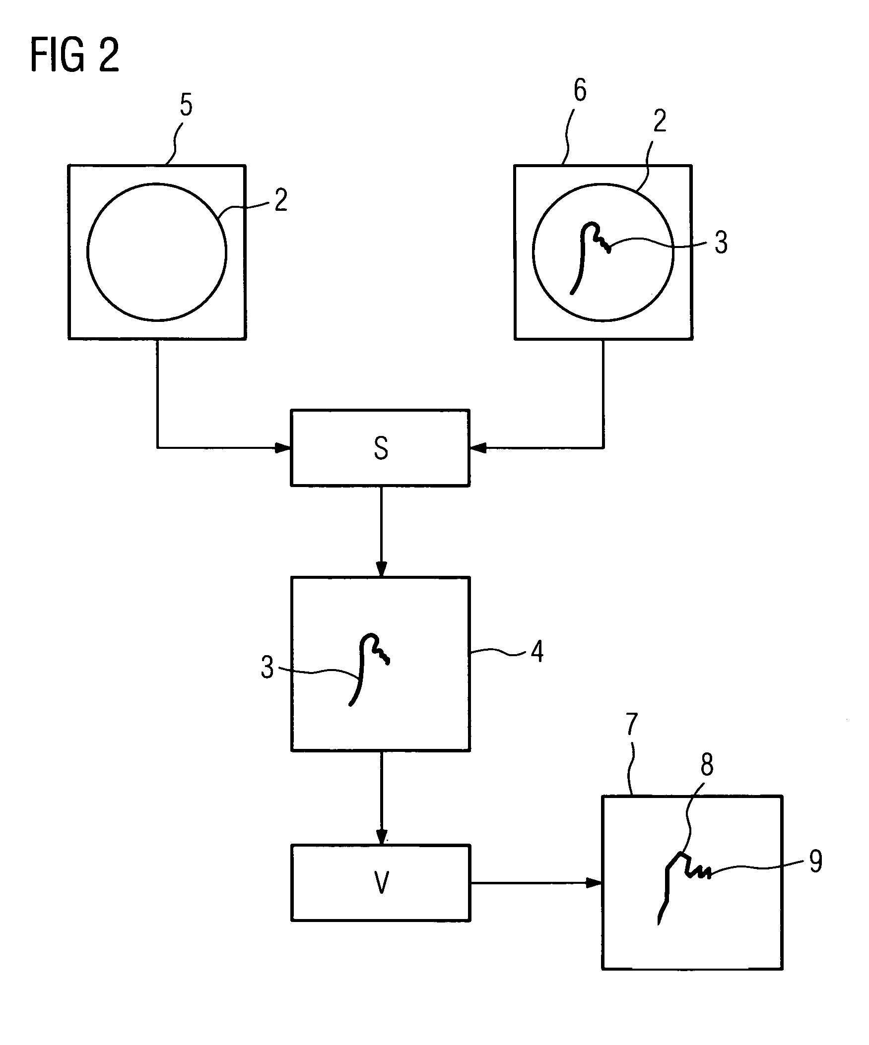
[0010]In the case of the method of the type described in the introduction the object is achieved by the characterizing features of the claims. The instrument image essentially shows the instrument inserted into the object under examination without background information. Vectorization of the instrument image allows the quantity of data to be reduced, whilst enhancing the quality of representation of the medical instrument and is carried out using an image processing system. The captured linear structure of the instrument image is thereby approximated by polylines.
[0027]Another option for a spatial representation without intra-operative acquisition of the object under examination is a previously generated 3D vascular model, which was generated as a mean model for a number of patients or ideally represents the vascular model of the patient to be treated. Three-dimensional location of the instrument can also be carried out in the vascular model, using the movement of the medical instrument and the capturing of the associated coordinates and / or coordinate changes. These options for spatial instrument representation in the object under examination assist medical personnel significantly during the medical intervention and primarily reduce the radiation load on the patient in the last-mentioned instance.

Problems solved by technology

On the one hand this method reduces subsequent image processing outlay and therefore computing time.

Method used


Image

  • Method for the graphical representation of a medical instrument inserted at least partially into an object under examination
  • Method for the graphical representation of a medical instrument inserted at least partially into an object under examination
  • Method for the graphical representation of a medical instrument inserted at least partially into an object under examination

Examples


Embodiment Construction

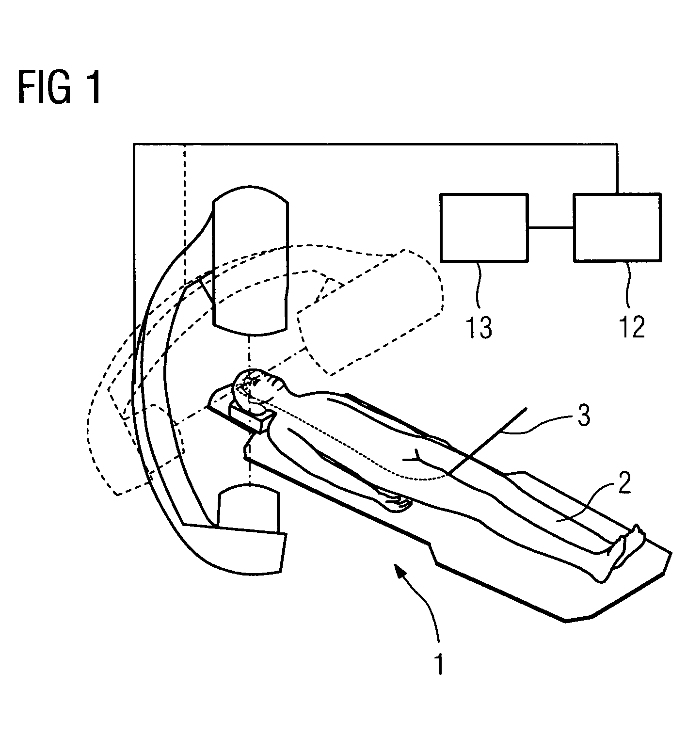
[0033]The arrangement shown in FIG. 1 for implementing the inventive method includes an examination device 1, here comprising a double C-arm x-ray system, having an acquisition device for an object under examination 2. The object under examination 2 is to be disposed on the acquisition device of the examination device 1 for execution of the inventive method such that the isocenter of the examination device 1 comes to lie where possible in the examination region of interest in the object under examination 2.

[0034]A medical instrument 3 is inserted into the object under examination 2, configured in the exemplary embodiment as a neurological guide wire. The neurological guide wire 3 is inserted into the vascular system of the object under examination 2 and navigated into the vascular system of the head. To control the intracranial position and location of the guide wire 3 in the object under examination 2, navigation is controlled by the examination device 1.

[0035]To this end a referen...


PUM


Abstract

The invention provides a method for the graphical representation of a medical instrument inserted at least partially into an object under examination, with an image representing the medical instrument being generated, in that the instrument image is vectorized, with the medical instrument being represented as a polyline.

Description

CROSS REFERENCE TO RELATED APPLICATIONS[0001]This application claims priority of German application No. 10 2005 044 405.9 filed Sep. 16, 2005, which is incorporated by reference herein in its entirety.FIELD OF THE INVENTION[0002]The invention relates to a method for a graphical representation of a medical instrument inserted at least partially into an object under examination.BACKGROUND OF THE INVENTION[0003]When a medical intervention is being carried out on an object under examination, perhaps a human or animal body, the status of the object under examination is generally controlled in a manner that is appropriate for the intervention risk. Body functions of the object under examination are recorded for this purpose. In the case ofan intervention with a medical device inserted at least partially into the object under examination, the position and / or optionally the location of the medical instrument within the object under examination is of interest as well as patient status.[0004]...

Claims


Application Information

Patent Timeline
IPC IPC(8): A61B5/05
CPCA61B6/12A61B19/52G06T7/004A61B6/4441A61B6/541A61B2019/5289G06T2207/10072G06T2207/30004G06T2207/30021A61B90/36A61B2090/364G06T7/70
Inventor PFISTER, MARCUSSANDKAMP, BERNHARD
Owner SIEMENS HEALTHCARE GMBH
Learn More