Methods of implanting a prosthetic mitral heart valve having a contoured sewing ring

a sewing ring and prosthetic technology, applied in the field of implantable prosthetic heart valves, can solve the problems of almost no attempts to improve the appearance of prosthetic valves

Active Publication Date: 2010-03-23
EDWARDS LIFESCIENCES CORP
View PDF26 Cites 33 Cited by
  • Summary
  • Abstract
  • Description
  • Claims
  • Application Information

AI Technical Summary

Benefits of technology

[0019]Preferably, the sewing ring comprises a suture-permeable annular member, and the step of implanting comprises suturing the sewing ring to the mitral valve annulus. For instance, the sewing ring may be a suture-permeable annular member surrounded by a fabric covering. The prosthetic mitral heart valve may have three axially-oriented commissures extending toward the outflow direction and into the ventricle when the valve is implanted, the first two commissures being located around the heart valve at the same locations as the two axially-raised portions and a third commissure being located equidistant from the first two. In this case, the method includes tilting the prosthetic mitral heart valve at an angle with respect to an annular plane such that the third commissure angles away from the adjacent ventricular wall and reduces the chance of contact therebetween.

Problems solved by technology

In particular, they have been almost no attempts to modify prosthetic valves to better conform to the mitral annulus.

Method used


Image

  • Methods of implanting a prosthetic mitral heart valve having a contoured sewing ring
  • Methods of implanting a prosthetic mitral heart valve having a contoured sewing ring
  • Methods of implanting a prosthetic mitral heart valve having a contoured sewing ring

Examples


Embodiment Construction

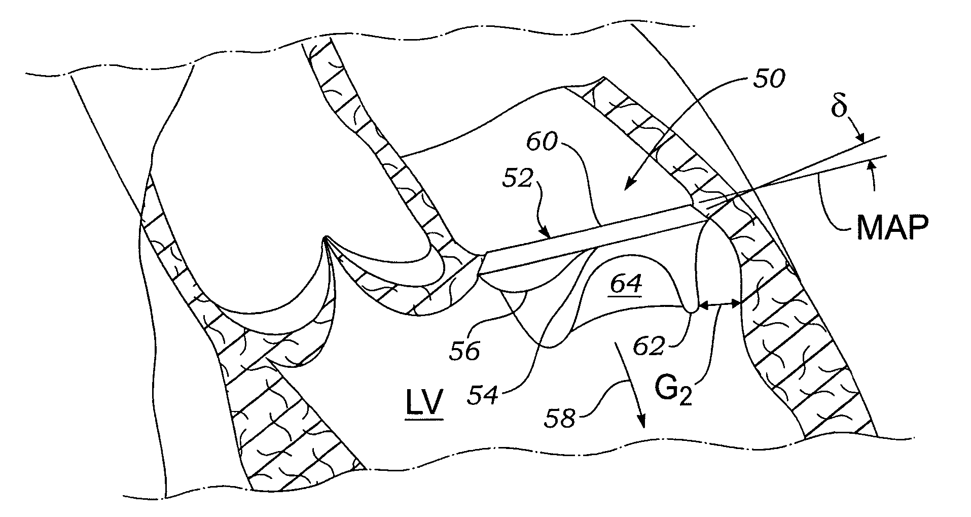
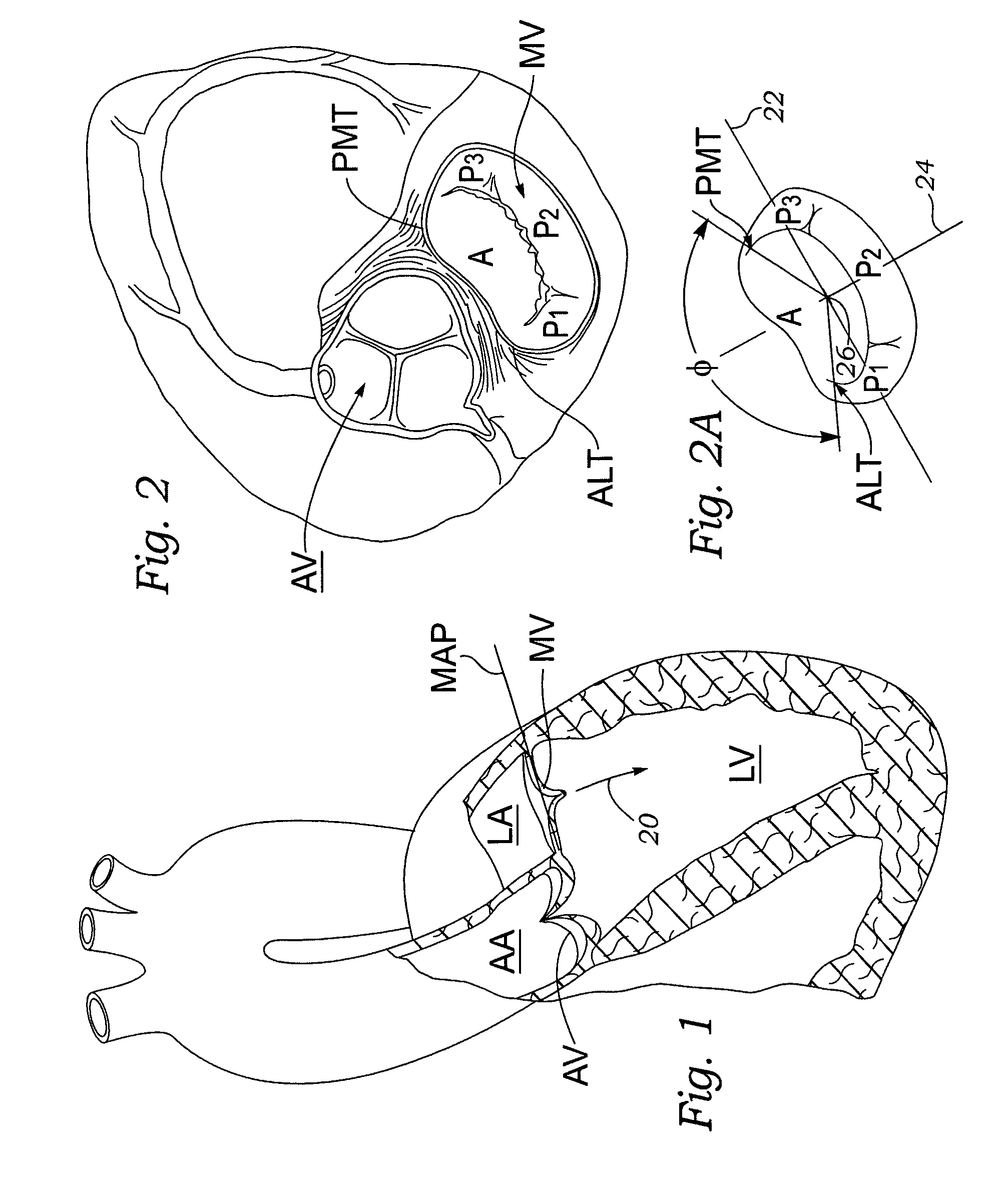
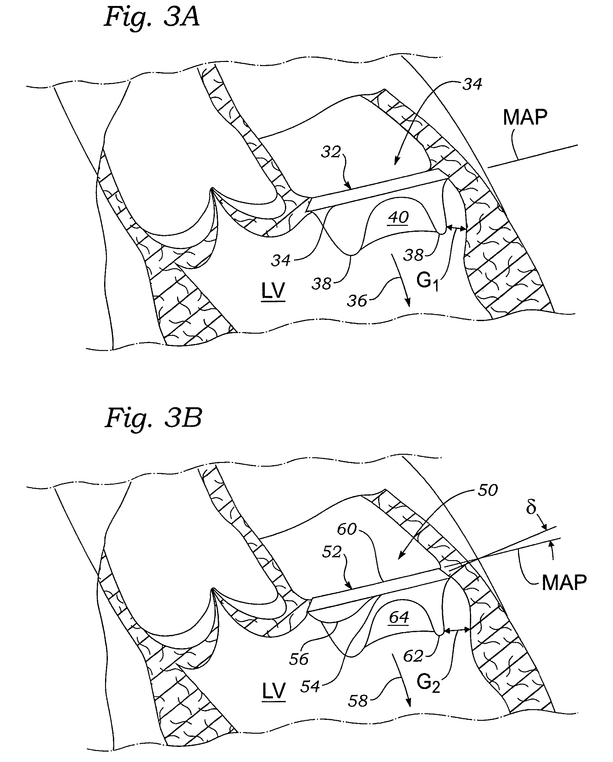
[0041]The present invention provides an improved prosthetic heart valve for the mitral annulus. The prosthetic heart valves disclosed herein have a contoured suture ring or sewing ring, sometimes known as a sewing cuff, that better matches the anatomy of the mitral annulus and also positions the valve at an angle relative to the annular plane. The sewing rings have at least one axially-raised portion on their outflow ends that matches up with the anterior aspect of the mitral annulus. In the illustrated embodiment, there are two such axially-raised portions, each corresponding to one of the fibrous trigones of the mitral annulus, while the posterior side of the outflow end is generally planar. It should be understood, however, that the posterior side of the outflow end may also be contoured or have a shape other than an annular plane.

[0042]The sewing ring disclosed herein is useful with any sort of prosthetic heart valve, bioprosthetic or mechanical, flexible leaflet or rigid leafle...


PUM


Abstract

A prosthetic mitral heart valve including a contoured sewing ring that better matches the mitral valve annulus. The sewing ring includes an inflow end and an outflow end, the outflow and having at least one raised portion. There may be two raised portions located approximately 120° apart from each other and designed to register with two anterior trigones of the mitral valve annulus. The sewing ring may be formed by a suture-permeable annular member surrounded by a fabric covering, the annular member desirably being molded of silicone. The raised portion(s) may gently curve upward to a height of about 2 mm above the adjacent portions of the outflow end of the sewing ring. The sewing ring may also be constructed so as to be more flexible around a posterior aspect than around an anterior aspect to accommodate calcified tissue more commonly found around the posterior annulus. The contoured sewing ring can be combined with various types of heart valve including bioprosthetic and mechanical valves. A bioprosthetic heart valve of the present invention may include a support stent having three outflow commissures alternating with three inflow cusps, with two of the commissures being located at the same place as two raised portions of the sewing ring. A method of implant includes tilting the prosthetic heart valve in the mitral annulus so that a posterior commissure angles away from the ventricular wall and reduces the chance of contact therebetween.

Description

FIELD OF THE INVENTION[0001]The present invention relates generally to an implantable prosthetic heart valve for the mitral annulus and, more particularly, to a contoured sewing ring for such a prosthetic heart valve.BACKGROUND OF THE INVENTION[0002]Two primary types of heart valve replacements or prostheses are known. One is a mechanical-type heart valve that uses a ball and cage arrangement or a pivoting mechanical closure supported by a base structure to provide unidirectional blood flow, such as shown in U.S. Pat. No. 6,143,025 to Stobie, et al. and U.S. Pat. No. 6,719,790 to Brendzel, et al., the disclosures of which is hereby expressly incorporated by reference. The other is a tissue-type or “bioprosthetic” valve having flexible leaflets supported by a base structure and projecting into the flow stream that function much like those of a natural human heart valve and imitate their natural flexing action to coapt against each other and ensure one-way blood flow. One example of a...

Claims


Application Information

Patent Timeline
Patent Type & Authority Patents(United States)
IPC IPC(8): A61F2/24
CPCA61F2/2409A61F2/2403A61F2250/0029A61F2250/0018A61F2/2412
Inventor JOHNSON, DERRICK
Owner EDWARDS LIFESCIENCES CORP
Why Eureka
Try Eureka