Generation device

a generation device and power supply technology, applied in the direction of electric generator control, electronic commutator, dynamo-electric converter control, etc., can solve the problems of inability to control the output of the generator, inability to adopt hall elements, and inability to control the cost, so as to reduce the cost of the generation device

Inactive Publication Date: 2010-03-23
KOKUSAN DENKI CO LTD
View PDF11 Cites 12 Cited by
  • Summary
  • Abstract
  • Description
  • Claims
  • Application Information

AI Technical Summary

Benefits of technology

[0025]The level of the phase current of the armature winding and the fixed point on the waveform of the phase current can be detected by a zero cross detection circuit or the like from the output of the current detector that detects the phase current. The rotational speed of the generator can be arithmetically operated from a cycle of detection of the fixed point on the waveform of the phase current. Thus, as described above, the phase angle of the fixed point on the waveform of the phase current of the magneto generator in relation to the reference phase is calculated, and the timing for generating the AC control voltage is decided with reference to the phase of the fixed point on the waveform of the phase current, and thus the AC control voltage can be generated without using a position sensor for detecting a rotational angle position of the rotor to control the output of the generator, thereby allowing the position sensor such as a magnetic sensor and a pulse signal generator to be omitted and reducing costs.
[0038]As described above, according to the present invention, the phase of the fixed point on the waveform of the phase current of the magneto generator in relation to the reference phase, or the phase of the fixed point on the waveform of the phase voltage in relation to the reference phase is calculated to decide the timing for generating the AC control voltage with reference to the phase of the fixed point on the waveform of the phase current or the phase of the fixed point on the waveform of the phase voltage. Thus, the AC control voltage can be generated without using the position sensor for detecting the rotational angle position of the rotor to perform control of the output of the generator by vector control. Thus, the position sensor such as a magnetic sensor or a pulse signal generator can be omitted to reduce costs of the generation device.

Problems solved by technology

However, in a magneto generator, a field is produced by a permanent magnet, and thus an output of the generator cannot be controlled by controlling the field in the same manner as the generator having the field winding.
As described above, in the conventional generation device using the vector control, the position sensor such as the magnetic sensor or the pulse signal generator needs to be provided for detecting the reference phase of the AC control voltage, which inevitably increases costs.
Generally, a hall element is used as the magnetic sensor, but the hall element is heat-sensitive and hard to adopt in the case where a prime motor such as an engine that causes much heat generation is used as a drive source of a magneto generator.
If many reluctors are thus provided in the rotor yoke of the generator, machining of the rotor yoke becomes troublesome, and the reluctors may interfere with each other to generate an error signal, which is unpreferable.

Method used


Image

  • Generation device
  • Generation device
  • Generation device

Examples


Embodiment Construction

[0049]Now, preferred embodiments of the present invention will be described in detail with reference to the drawings.

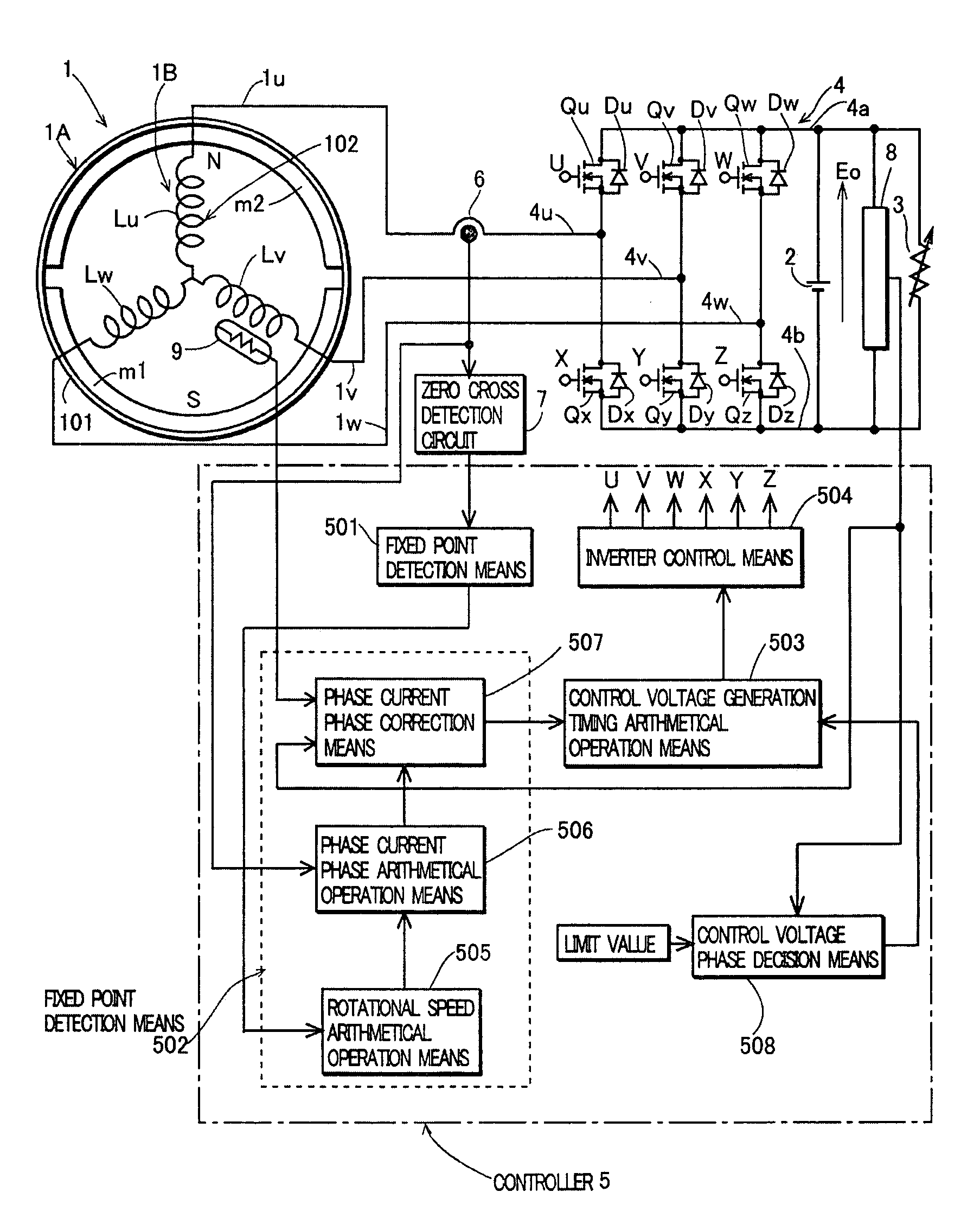
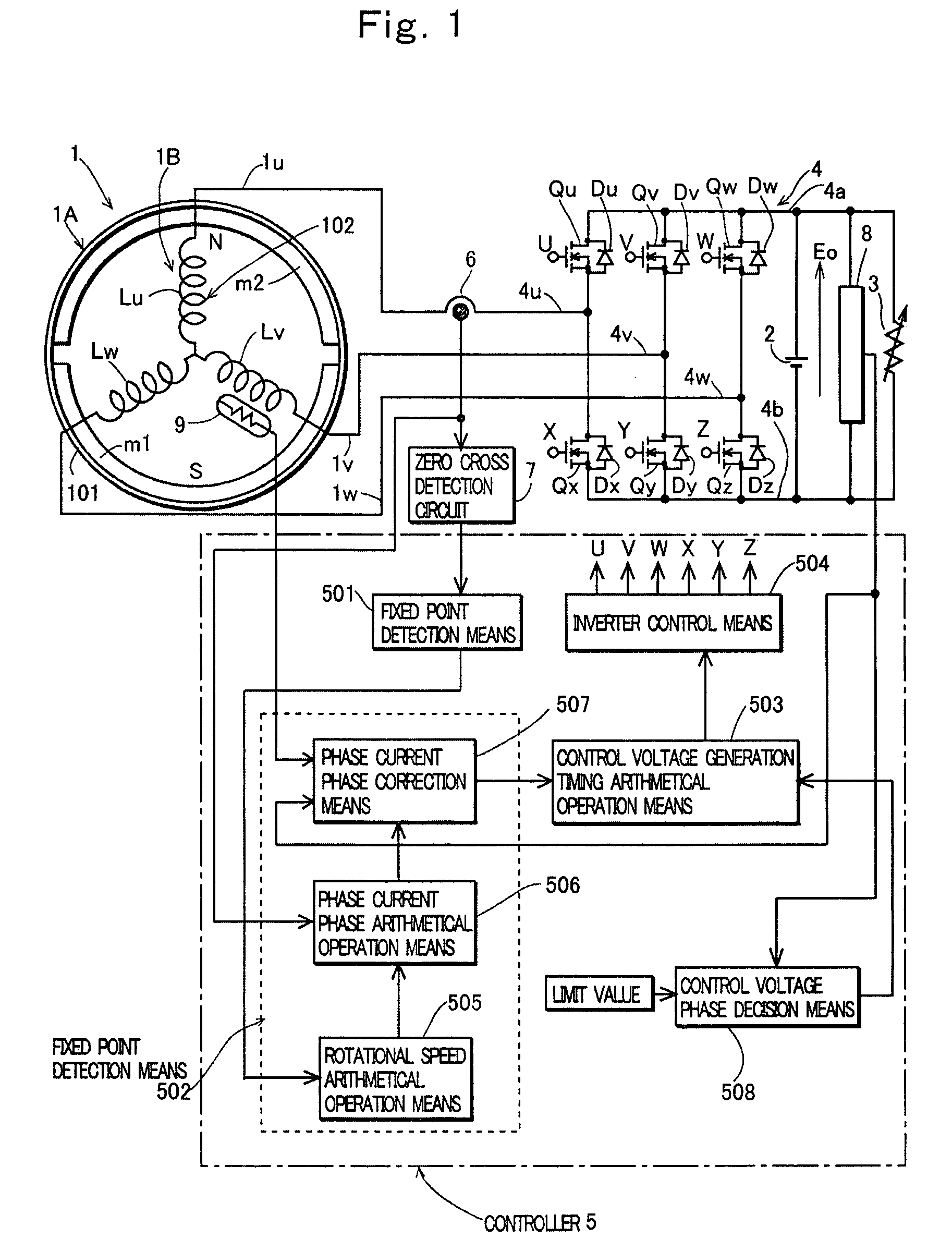
[0050]FIG. 1 is a block diagram of a construction of a preferred embodiment of a generation device according to the present invention. In FIG. 1, 1 denotes a magneto generator driven by an engine, 2 denotes a battery as voltage accumulation means, 3 denotes a load connected across the voltage accumulation means 2, 4 denotes an inverter provided between the magneto generator 1 and the voltage accumulation means 2, 5 denotes a controller that controls the inverter, 6 denotes a current detector that detects a phase current of the magneto generator 1, 7 denotes a zero cross detection circuit that detects a zero cross point of the phase current detected by the current detector 6, 8 denotes a voltage detector that detects a voltage across the voltage accumulation means 2, and 9 denotes a temperature sensor that detects a temperature of an armature winding of the magneto gen...


PUM


Abstract

A generation device, having a magneto generator, in which an AC control voltage is applied from a battery charged with a rectified output of the magneto generator to an armature winding of the generator through an inverter to control a battery voltage to a limit value or less, comprising: fixed point detection means for detecting a fixed point on a waveform of a phase current of the generator; phase current phase detection means for detecting a phase angle of the fixed point in relation to a reference phase; arithmetical operation means for arithmetically operating timing for generating the AC control voltage with reference to the phase of the fixed point; and inverter control means for controlling switch elements of the inverter so as to generate the AC control voltage at the timing arithmetically operated by the arithmetical operation means.

Description

TECHNICAL FIELD OF THE INVENTION[0001]The present invention relates to a generation device that drives a load with a rectified output of a magneto generator.PRIOR ART OF THE INVENTION[0002]In driving a load with a rectified output of a generator, the output of the generator needs to be controlled so that a voltage across the load does not exceed a limit value for protecting the load from overvoltage. When the generator has a field winding, a current passing through the field winding can be controlled to control the output of the generator. However, in a magneto generator, a field is produced by a permanent magnet, and thus an output of the generator cannot be controlled by controlling the field in the same manner as the generator having the field winding.[0003]Thus, the applicant has proposed a generation device comprising a voltage type inverter between an armature winding of a magneto generator and voltage accumulation means (a battery or a capacitor) connected in parallel with a ...

Claims


Application Information

Patent Timeline
Patent Type & Authority Patents(United States)
IPC IPC(8): H02P9/44H02M3/36
CPCH02P6/16H02P9/30
Inventor INABA, YUTAKANAKAGAWA, MASANORI
Owner KOKUSAN DENKI CO LTD
Why Eureka
Try Eureka