
Movable shade assembly for watercraft

a shade assembly and watercraft technology, applied in the field of movable and/or adjustable shade assembly, can solve the problems of not being able to generate much excitement, people and/or children riding on boats do not enjoy sitting in the sun for long periods, are uncomfortable, hot and/or sweaty, etc., and achieve the effect of facilitating its selective disposition

Active Publication Date: 2010-03-30
CARUSELLO KENNETH J +1
View PDF4 Cites 10 Cited by
  • Summary
  • Abstract
  • Description
  • Claims
  • Application Information

AI Technical Summary

Benefits of technology

[0013]More specifically, each of the plurality of preferred embodiments of the present invention is directed to a shade assembly designed to be movably and / or adjustably mounted at any of a plurality of different locations on a watercraft. As such, the adjustable nature of the shade assembly of the present invention allows it to be disposed in any one of a plurality of operative positions by adjustment of the orientation of a cover assembly thereof, while in a single, predetermined position. Alternatively at least some of the various embodiments of the shade assembly are structured to be quickly and easily removably connected to different portions and / or locations on the watercraft when needed to protect selected parts of the watercraft from exposure to the sun or other weather conditions.
[0016]Therefore, the aforementioned plurality of different operative positions may be easily accomplished by the adjustable movement or positioning of the adjustment assembly, relative to respective ones of the mounting assemblies serving to interconnect the shade assembly to the aforementioned, substantially common, predetermined portion of the watercraft.
[0020]A structural modification of this and possibly other preferred embodiments, which defines yet another preferred embodiment, comprises the cover assembly including a single support arm having an arcuate or other predetermined configuration extending about a “leading” portion of the periphery of the cover member. In addition, opposite longitudinal ends of the single support arm are secured to different ones of two, spaced apart attachment devices. In turn, each of the attachment devices may be movably and adjustably connected to corresponding ones of two different mounting assemblies by virtue of an adjustment assembly. As with others of the preferred embodiments of the present invention, the cooperatively disposed mounting assemblies may be removably connected to a substantially common portion of the watercraft and are easily detached therefrom so as to relocate the shade assembly to any of a plurality of other locations on the watercraft.
[0023]Another distinguishing structural and / or operative feature of this additional preferred embodiment of the shade assembly of the present invention includes two channels or other receiving members on each attachment device such that the support arm may be selectively secured and disposed within the channels either laterally or transversely relative to the attachment device. As with the other preferred embodiments of the present invention, the cooperatively disposed mounting assemblies may be removably connected to a substantially common portion of the watercraft and may be easily detached therefrom so as to relocate the shade assembly to any of a plurality of other locations on the watercraft.
[0026]Based on the above and on a further more detailed description of the various preferred embodiments of the shade assembly of the present invention, many if not all of the disadvantages and problems associated with conventional shade structures on various types of watercraft are overcome. More specifically, the operative and structural versatility of the shade assembly of the present invention facilitate its selective disposition in any one of a plurality of operative, protective positions so as to accommodate orientations of the watercraft, on which it is mounted, and the sun. Such versatility allows an operator of the shade assembly of the present invention the ability to selectively protect different exterior deck areas or other exterior portions of the watercraft from exposure to the sun or other weather conditions.

Problems solved by technology

However, as participants of an outdoor activity, individuals driving or riding in the various types of watercraft, hereinafter referred to as boaters, are subjected to the direct effects of the weather and often for extended periods of time.
In addition, it is well known that some people and / or children riding on boats do not enjoy sitting in the sun for long periods and become uncomfortable, hot and / or sweaty after only a short period of time.
As a result, a boating or fishing enthusiast may find that his / her invitation to have friends and family, spend a day out on the boat, may not generate much excitement.
Consequently, the remaining portions of the watercraft, such as the bow and the rear or stern portions are generally exposed to direct sunlight, rain and / or other effects of the weather.
Additionally, there may be a general tendency for the bow of the boat to swing, turn into the wind or otherwise be reoriented while anchored or drifting.
This will frequently result in different exterior portions of the craft being exposed to the sun.
Under normal operating conditions of the type set forth herein, the ability to control or direct the angle of the sun relative to the orientation of the boat is limited.
Accordingly, many substantially fixed shade or cover structures such as, but not limited to, the aforementioned “T-Top” structures, are inadequate for the purpose of providing sufficient shade for many if not the majority of exterior portions of a watercraft.

Method used


Image

  • Movable shade assembly for watercraft
  • Movable shade assembly for watercraft
  • Movable shade assembly for watercraft

Examples


Embodiment Construction

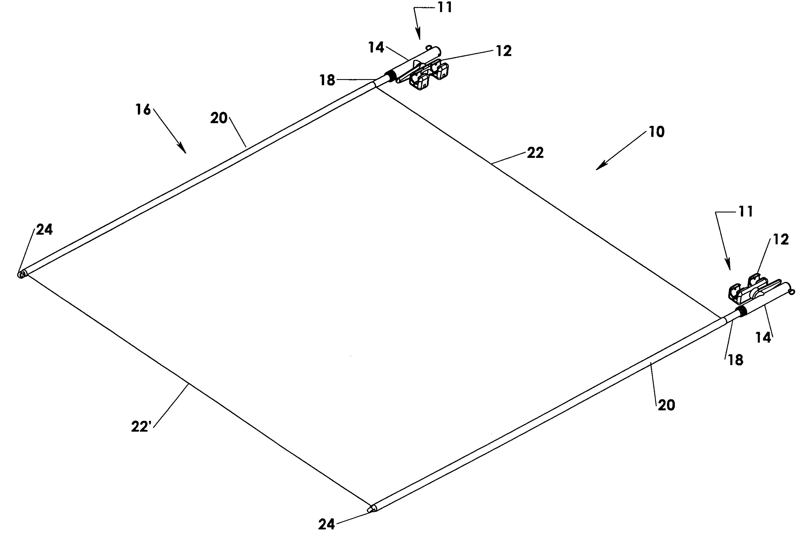
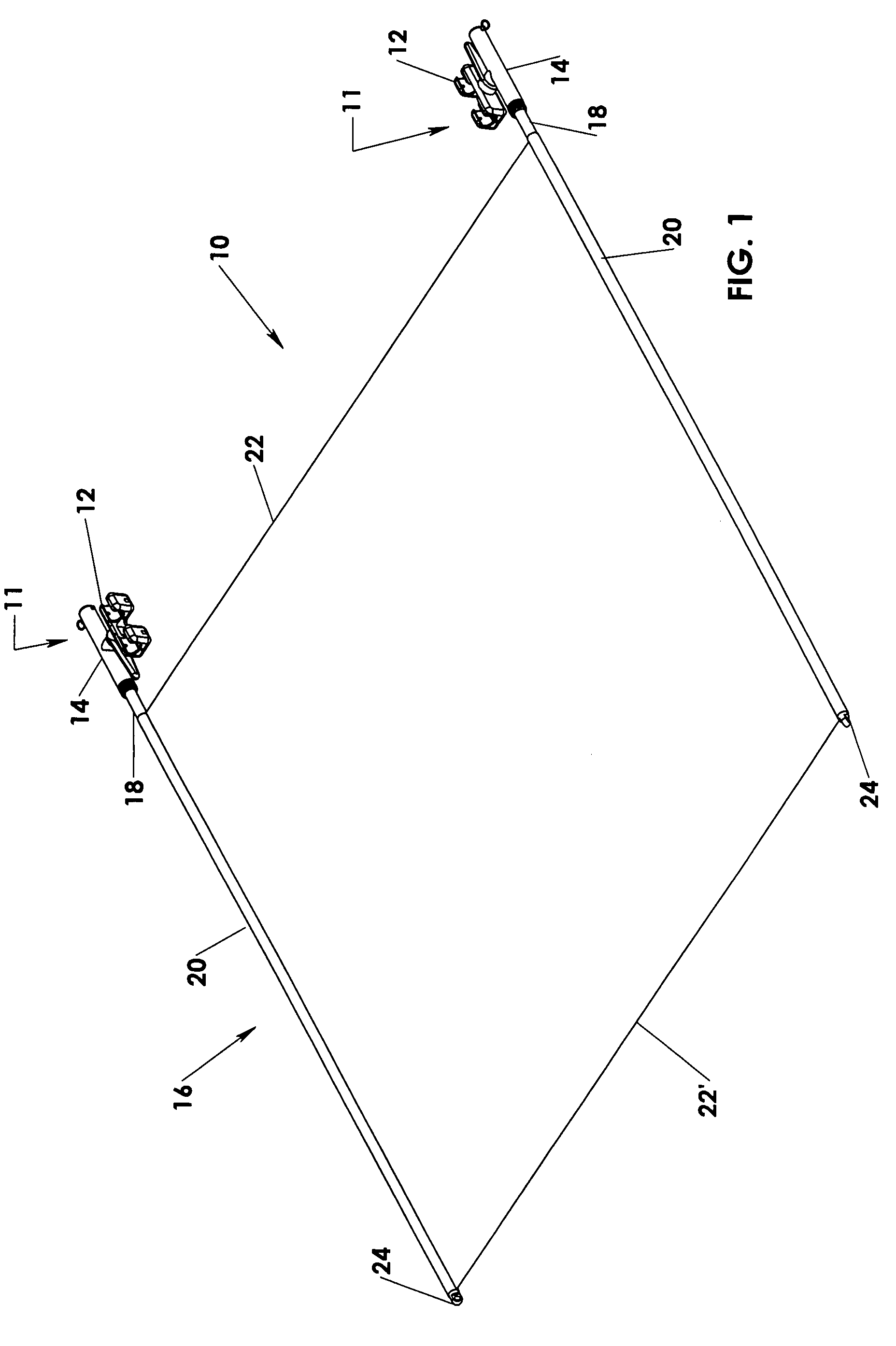
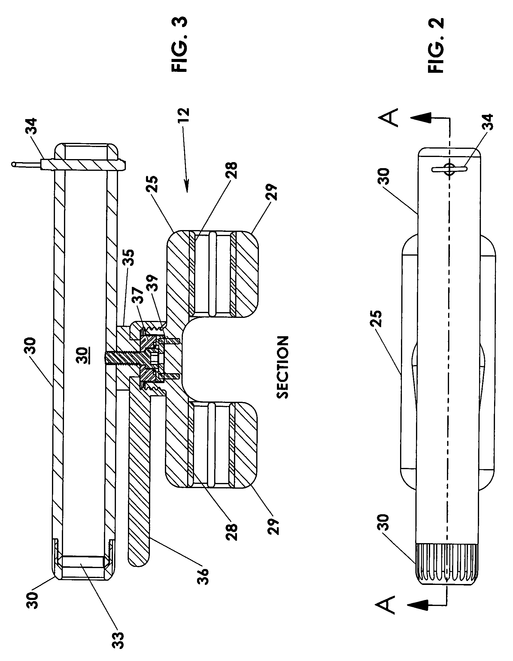
[0082]As shown in the accompanying drawings, the present invention is directed to a shade assembly wherein at least one preferred embodiment is generally indicated as and shown in detail in FIGS. 1 through 4. More specifically, the shade assembly 10 includes at least one, but more practically a plurality of two attachment devices 11, each having at least one mounting assembly 12. Each of the mounting assemblies 12 are structured to be removably connected to a predetermined portion of a watercraft. The versatility of the structure and operation of each of the mounting assemblies 12, as represented in detail in FIGS. 1 through 4, facilitate the removable attachment or connection of the shade assembly 10 to various portions of the watercraft and / or structure associated with the watercraft. By way of example only, the mounting assemblies 12 may be removably secured to the tubular frame portion(s) of a radar arch, “t-top”, “Bimini top” or like canvas or other material shading structures ...


PUM


Abstract

A shade assembly for a watercraft comprising at least one attachment device and a cover assembly. The attachment device includes at least one mounting assembly structured to be connected to any one of a plurality of predetermined portions of the watercraft. The cover assembly is structured to provide protection of various parts of the watercraft from at least sun exposure by producing a shaded area. At least one adjustment assembly is disposed in interconnecting relation between the mounting assembly and the cover assembly, and is structured to selectively dispose said the cover assembly in any one of a plurality of operative positions relative to the mounting assembly and the various parts of the watercraft.

Description

CLAIM OF PRIORITY[0001]The present application is based on and a claim of priority is made under 35 U.S.C. Section 119(e) to provisional patent application currently pending in the U.S. Patent and Trademark Office having Ser. No. 60 / 783,780 and a filing date of Mar. 17, 2006.BACKGROUND OF THE INVENTION[0002]1. Field of the Invention[0003]This invention relates to a movable and / or adjustable shade assembly which can be attached to watercraft of different sizes, styles and configurations so as to provide shade and / or shelter to portions of the craft normally exposed to various weather conditions. The various embodiments of the shade assembly may comprise a cover assembly and an attachment device, which may have at least one mounting assembly and one or more adjustment assemblies cooperatively structured to selectively shade or otherwise protect various exposed areas of the craft by an adjustable and / or movable disposition of the cover assembly into any one of a plurality of operative ...

Claims


Application Information

Patent Timeline
IPC IPC(8): B63B17/00
CPCB63B17/02
Inventor CARUSELLO, KENNETH J.ALVAREZ-FUENTES, GERMAN
Owner CARUSELLO KENNETH J
Learn More