Combustion-gas-powered paintball marker

a paintball marker and combustion gas technology, applied in the field of combustion gas powered paintball markers, can solve the problems of limiting the number of shots (pressure pulses) that can be fired from the markers to a level that is not acceptable to most users, high-pressure containers, and large high-pressure containers, etc., and achieves short time sufficient, high turbulence, and increased burn rate of combustion gases.

Inactive Publication Date: 2010-03-30
ADAMS JOSEPH S
View PDF57 Cites 21 Cited by
  • Summary
  • Abstract
  • Description
  • Claims
  • Application Information

AI Technical Summary

Benefits of technology

[0013]For producing gas pressure pulses of sufficient energy within a gas-powered engine of limited dimensions, the engine preferably includes a combustion accelerating system for increasing the burn rate of combustion gases. The combustion accelerating system is preferably located within a cylinder head and includes a displacer such as a mixing piston that redistributes space between a mixing chamber and a combustion chamber. Movement of the mixing piston in a first direction draws air into the mixing chamber and displaces exhaust gases from the combustion chamber. Movement of the mixing piston in a second direction transfers a charge of fuel and air from the mixing chamber into the combustion chamber for producing a turbulent charge in the combustion chamber. Combustion within the combustion chamber is accelerated by the turbulence, allowing for the generation of a high peak pressure over a short time sufficient for propelling a paintball. A check valve can be used to prevent any return flows from the combustion chamber into the mixing chamber.
[0030]A pulse-shaping system preferred for the launcher features a connection between the combustion chamber and the barrel of the launcher for communicating a pressure pulse generated within the combustion chamber to the barrel for launching a projectile. A valve interrupts the connection between the combustion chamber and the barrel for shaping a pressure profile of the pressure pulse before launching the projectile. The combustion chamber preferably includes an exit port and the valve preferably regulates flows of combustion gas through the exit port. The preferred valve is closed at a start of combustion within the combustion chamber and is opened by combustion pressure within the combustion chamber. Two relatively moveable members of the valve provide for varying flow rates through the valve as the valve is opened between fully closed and fully opened positions. Since the paintballs are necessarily somewhat fragile, the ability to shape the pressure-as-a-function-of-time profiles of the combustion-generated pressure pulses assures that the paintballs are safely launched under optimum pressure conditions.

Problems solved by technology

A number of problems are associated with the practice of deriving gas pressure pulses from portable supplies of compressed gas as well as with the practice of transporting compressed gas supplies.
However, the limited amount of compressed gas severely restricts the number of shots (pressure pulses) that can be fired from the markers to a level that is not acceptable to most users.
In addition to the difficulty and inconvenience of transporting large containers, the transport of high-pressure containers, particularly large high-pressure containers, poses significant safety concerns.
Typical gas pressures range from 700 psi (pounds per square inch) to 4000 psi, and such high-pressure containers are potentially very dangerous and must be handled carefully to avoid accidents.

Method used


Image

  • Combustion-gas-powered paintball marker
  • Combustion-gas-powered paintball marker
  • Combustion-gas-powered paintball marker

Examples


Embodiment Construction

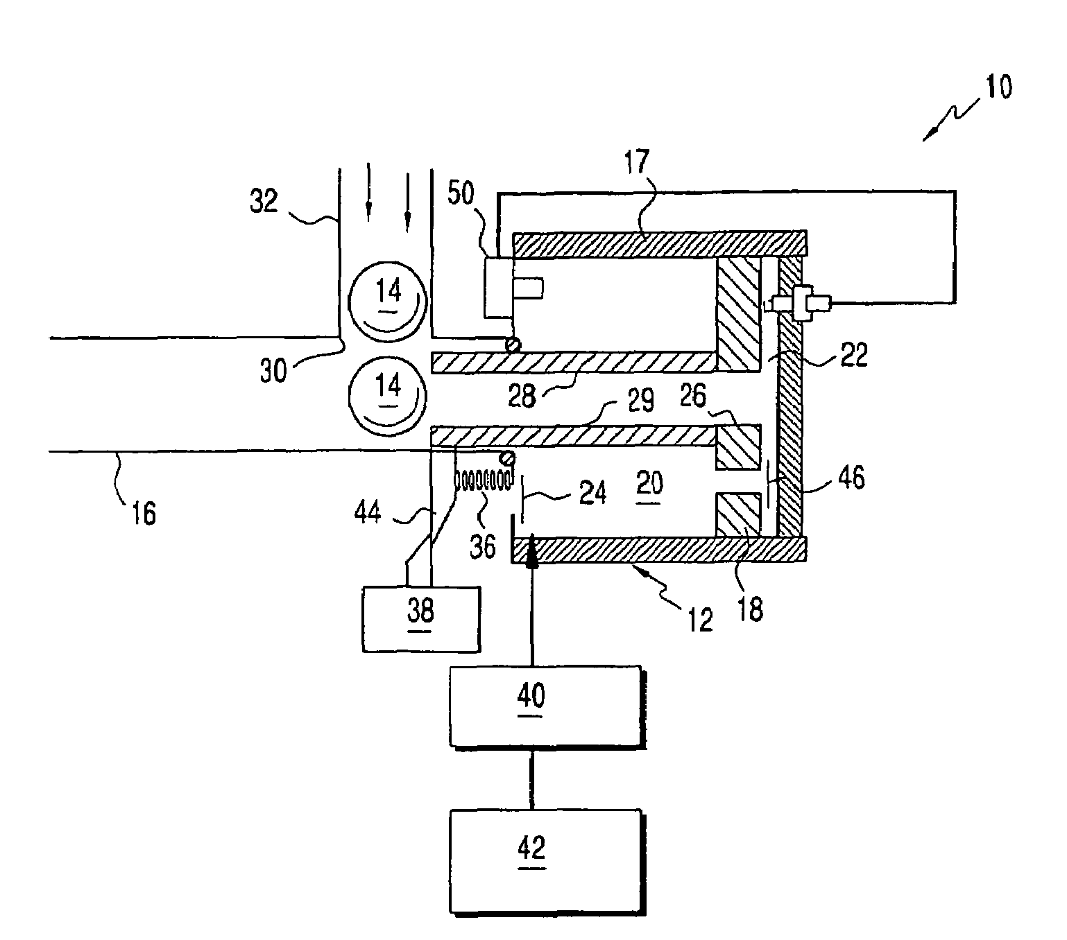
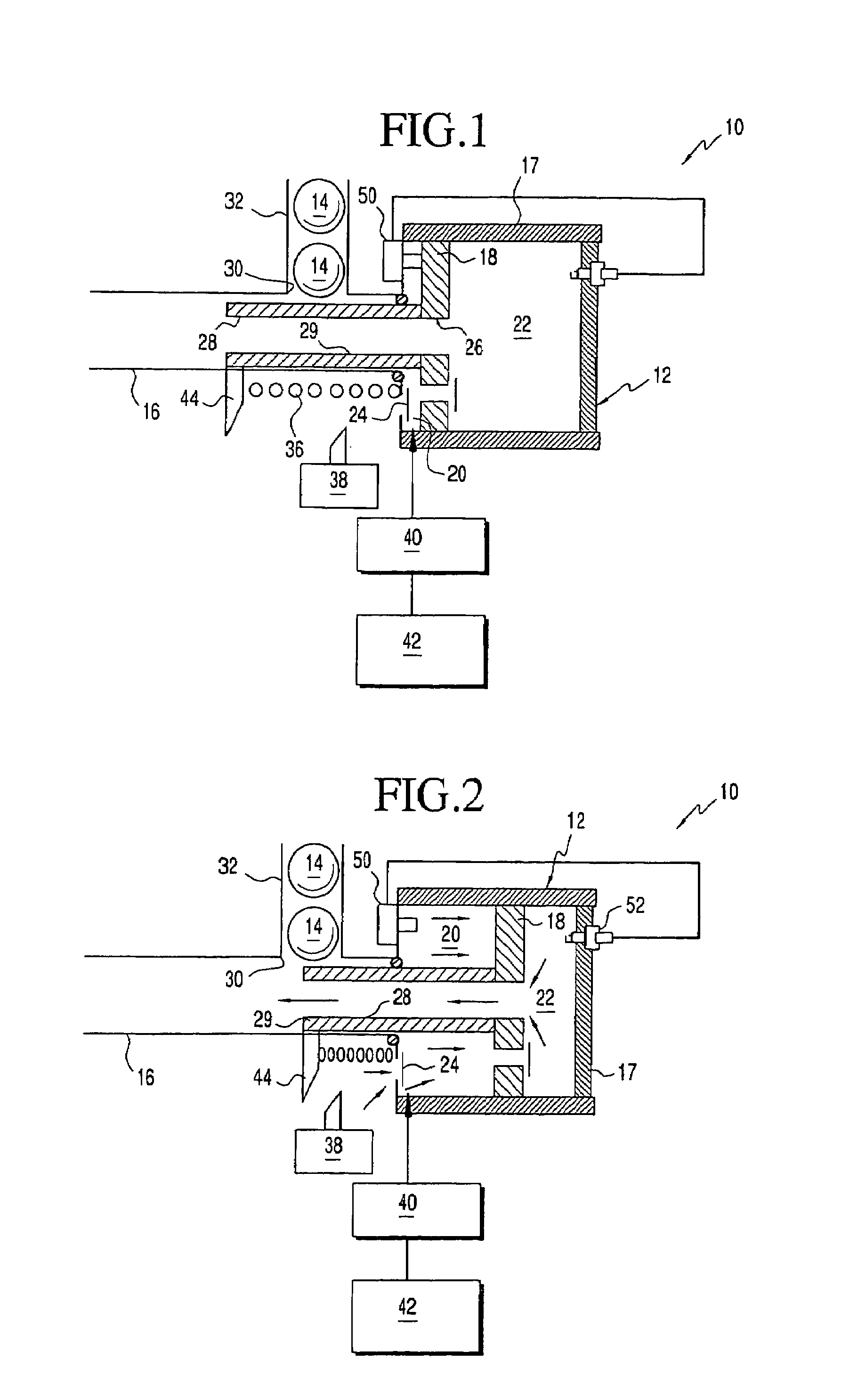
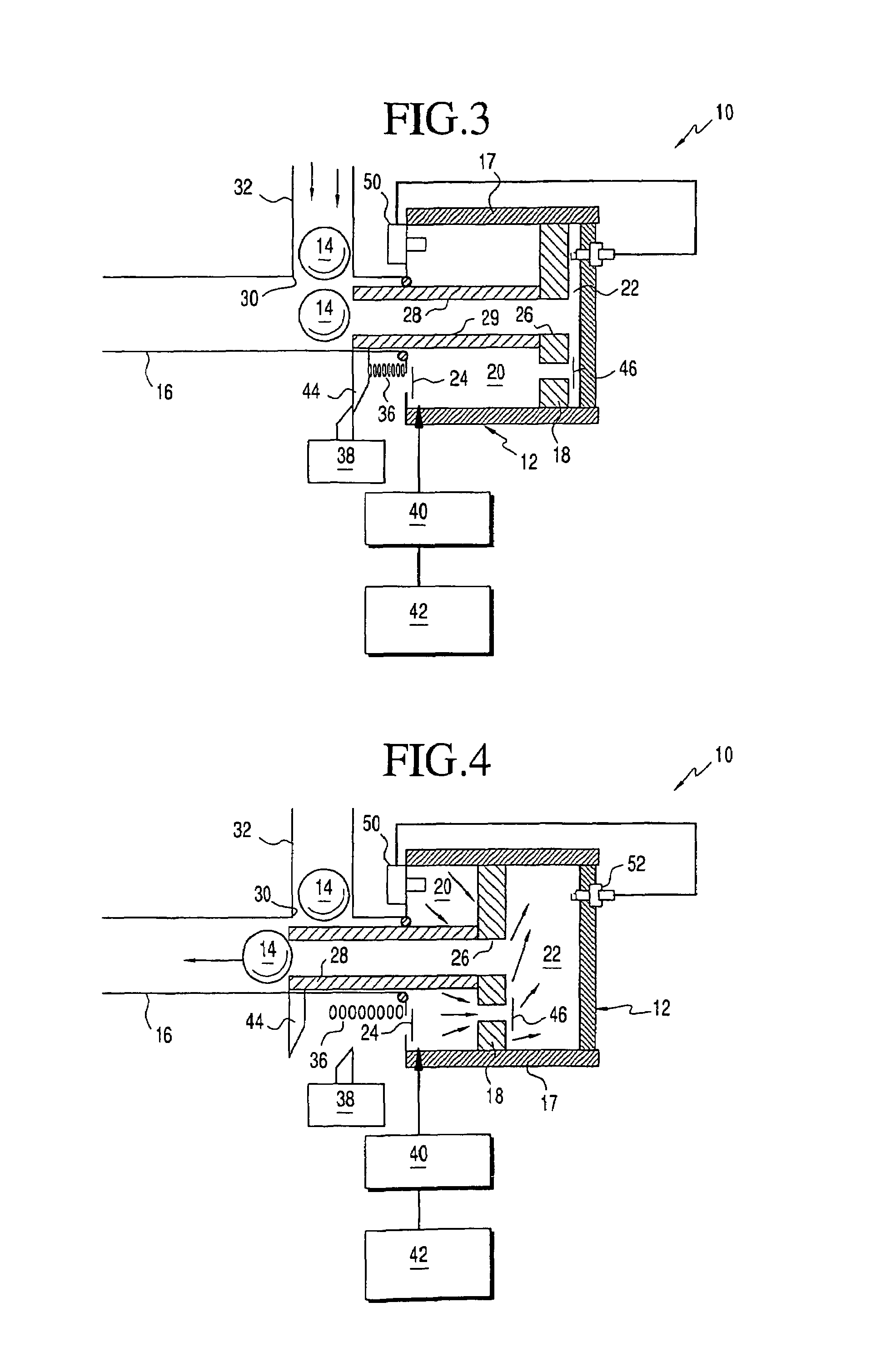
[0055]A paintball marker 10 in accordance with one version of my invention is shown in FIGS. 1 through 6 in which an onboard combustion-gas-powered engine 12 generates combustion-gas-pressure pulses for propelling paintballs 14 from a barrel 16. The engine 12 includes a cylinder head 17 having an interior space that is divided by a displacer in the form of a mixing piston 18 into a mixing chamber 20 and a combustion chamber 22.

[0056]Movement of the mixing piston 18 in a first direction as shown in FIGS. 1 through 3 expands the mixing chamber 20 drawing in ambient air through a check valve 24 into the mixing chamber 20 and contracts the combustion chamber 22 displacing any exhaust gases from the combustion chamber 22 through an exit port 26 in the mixing piston 18. A discharge conduit 28 is connected to the mixing piston 18 in communication with the exit port 26 for conveying the exhaust gases out the barrel 16. The discharge conduit 28 is formed within a bolt 29 whose retraction in ...


PUM


Abstract

An onboard combustion-gas-powered engine supplies power to a paintball marker or other projectile launcher by generating gas pressure pulses for propelling paintballs and other projectiles. The combustion gases produced by the engine can be allowed to rise in pressure within a confined volume of space before being released through a valve into a barrel for applying enhanced pressure pulses to the projectiles. A loading system is linked to a combustion accelerating system for automatically loading projectiles into the launcher.

Description

CROSS-REFERENCE TO RELATED APPLICATIONS[0001]This patent application is a Divisional patent application of prior U.S. patent application Ser. No. 10 / 760,922, which was filed on Jan. 20, 2004.[0002]Priority is claimed to Provisional Application No. 60 / 443,520, filed 29 Jan. 2003, the disclosure of which is hereby incorporated by reference.BACKGROUND OF INVENTION[0003]1. Field of the Invention[0004]Propulsion systems of paintball markers generally provide for discharging gas pressure pulses for propelling paintballs. Such pressure pulses in accordance with this invention are produced by gas-powered engines. Similar propulsion systems can be applied to other projectile launchers such as air guns, air soft guns, simmunitions, training guns, as well as other fuel cell powered launchers.[0005]2. Description of Related Art[0006]Conventional paintball markers include pneumatic launching systems powered by portable supplies of compressed gas, such as CO2, air, or nitrogen, mounted directly o...

Claims


Application Information

Patent Timeline
Patent Type & Authority Patents(United States)
IPC IPC(8): F41B11/00F41A1/04F41A5/34F41B11/02F41B11/32
CPCF41A1/04F41A5/34F41B11/721F41B11/57F41B11/52F41B11/71
Inventor ADAMS, JOSEPH S.
Owner ADAMS JOSEPH S
Why Eureka
Try Eureka