Image reading apparatus

a reading device and image technology, applied in the field of compact image reading devices, can solve the problems of user inconvenience, battery life is not as long as expected, and the user feels inconvenience, etc., and achieve the effect of prolonging the use time and not wasting the battery

Inactive Publication Date: 2010-03-30
FUJITSU LTD
View PDF23 Cites 2 Cited by
  • Summary
  • Abstract
  • Description
  • Claims
  • Application Information

AI Technical Summary

Benefits of technology

[0015]The present invention has been developed to solve the above mentioned problems, and aims at providing an image reading apparatus for use in an image reading process apparatus to be used by attaching a compact image reading apparatus to mobile information equipment with batteries working for a longer time and the apparatus operating conveniently.
[0017]Thus, during the image reading operation of the image reading apparatus, the unnecessary illumination of the backlight of the display device of the information processing device can be reduced or turned off to reduce the intensity of the display device, thereby successfully providing an image reading apparatus for reducing the power consumption of a power supply built in the information processing device.
[0019]Thus, depending on the state of a reading operation of the image reading apparatus, the supply of the power supply or the operation clock signal of the information processing device can be limited or stopped on the portion not related to the reading operation. Therefore, an image reading apparatus capable of reducing the power consumption of the power supply built in the conjunctive information processing device can be provided.
[0022]Thus, depending on the state of a reading operation of the image reading apparatus, the direction of the notification display of the information processing device can be changed into a user convenient direction, the lighting-up notification of a lamp can be given, or a notification alarm can be given, thereby successfully providing a user-convenient image reading process apparatus.
[0024]Thus, depending on the state of a reading operation of the image reading apparatus, an unnecessary inputting process is invalidated during the image reading operation, and the information processing device during the image reading operation, that is, the scanner can be more freely picked up by hand, thereby successfully providing a user-convenient image reading process apparatus.
[0026]Thus, the use of the power supply to each function block is variably controlled depending on the state of a reading operation, and the using time can be extended to the longest possible time length without wasting the battery.

Problems solved by technology

However, batteries cannot work for a long time as expected by users, and conventional mobile information equipment often leaves much to be desired because it easily indicates battery exhaustion.
As a result, there has been the problem that the user feels inconvenience when the scanner is incorporated into the mobile information equipment.
Therefore, although it is not necessary to turn on the backlight of the display device, the backlight is unnecessarily turned on in the conventional technology, thereby accelerating the wasteful power consumption.

Method used


Image

  • Image reading apparatus
  • Image reading apparatus
  • Image reading apparatus

Examples


first embodiment

[0056]FIG. 4 is a block diagram showing the function of the image reading process apparatus in which the image reading apparatus 10 and the PDA 20 are incorporated into one unit basically functioning as described above according to the In the block diagram of the functions as shown in FIG. 4, the function blocks relating to the similar functions to the those of the hardware configuration shown in FIG. 3A are assigned the reference numerals corresponding to those assigned in the hardware configuration shown in FIG. 3A.

[0057]As shown in FIG. 4, the function according to the first embodiment of the image reading process apparatus in which the image reading apparatus 10 and the PDA 20 are incorporated into one unit is formed by: a read control unit 16 as a read control device for controlling a read of an image by the image reading apparatus 10; a display unit 25 as a display device for display-driving the LCD device of the input display unit 21 of the PDA 20; an illuminating unit 26 fo...

second embodiment

[0062]FIG. 5 is a block diagram of the function of the image reading apparatus 10 according to the Also in FIG. 5, the function blocks relating to the similar functions to the those of the hardware configuration shown in FIG. 3A are assigned the reference numerals corresponding to those assigned in the hardware configuration shown in FIG. 3A.

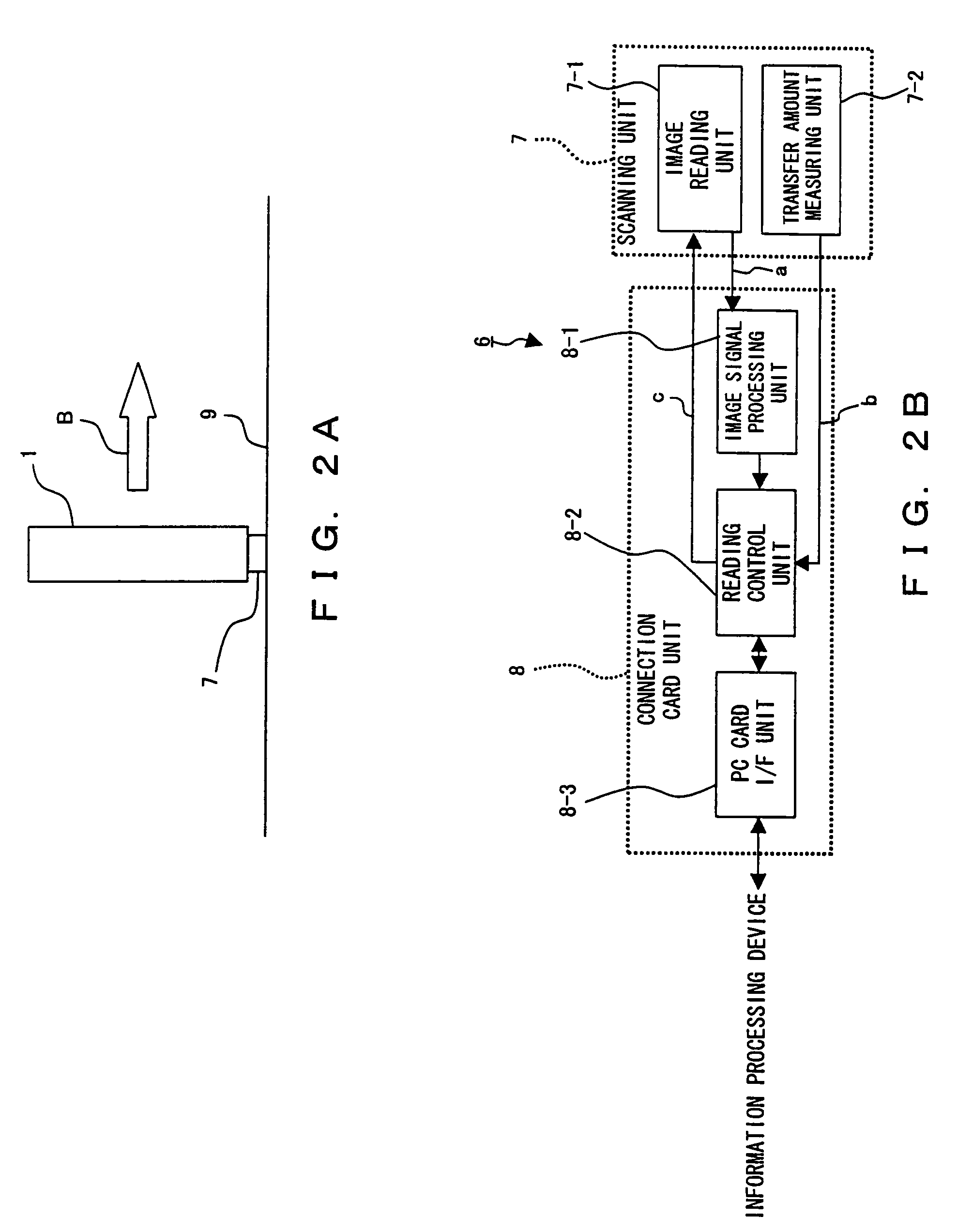
[0063]As shown in FIG. 5, the function block of the image reading apparatus 10 comprises an image reading unit 11-1 of the scanner unit 11, a transfer amount detection unit 11-2, an original document detection unit 11-3, an image signal process unit 12-1 of the connection card unit 12, a reading control unit 12-2 as a read control device, a device I / F unit 12-3, and a power supply control unit 12-4. Actually, the scanner unit 11 also comprises an image signal process unit functioning in conjunction with the image signal process unit 12-1 of the connection card unit 12, but they are shown in FIG. 5 as included in the image signal process unit 12...

third embodiment

[0075]FIG. 7 is a block diagram showing the function of the image reading apparatus 10 according to the Also in FIG. 7, the function blocks relating to the similar functions to the those of the hardware configuration shown in FIG. 3A are assigned the reference numerals corresponding to those assigned in the hardware configuration shown in FIG. 3A.

[0076]Furthermore, in FIG. 7, the power supply control unit 12-4 of the function block in FIG. 5 is replaced with a clock control unit 12-5, and a clock signal m transmitted from the clock control unit 12-5 to each function block is controlled depending on the image reading state.

[0077]The processing operations are almost the same except that the power supply control unit 12-4, the power supply control signal k, and the power supply shown in FIGS. 5 and 6 are respectively replaced with the clock control unit 12-5, the clock signal m, and the supply of a clock signal.

[0078]Thus, by controlling a clock signal to be supplied to each function ...


PUM


Abstract

An image reading apparatus is attached to the top of a PDA. During the image reading operation, an operation state control signal is output from the image reading apparatus to the PDA. According to the signal, the intensity of an input display unit not required during the operation can be reduced. Additionally, the power supply or the supply of a signal not required during the operation is stopped. Furthermore, an LED of the PDA issues a notification of an operation state by lighting, blinking, or turning-off. When the input display unit displays an image, an erect image and an inverted image are appropriately switched depending on the operation state. During an image reading operation, input by input buttons and a touch panel of the input display unit are nullified to avoid the occurrence of a malfunction.

Description

CROSS REFERENCE TO RELATED APPLICATION[0001]This application is a continuation of application Ser. No. 10 / 419,183, filed Apr. 21, 2003, now U.S. Pat. No. 6,886,749 now allowed.BACKGROUND OF THE INVENTION[0002]1. Field of the Invention[0003]The present invention relates to a compact image reading apparatus which is attached to a personal digital assistant (PDA) and reads an image.[0004]2. Description of the Related Art[0005]FIGS. 1A, 1B, and 1C show the configuration of a conventionally well-known compact image reading process apparatus. FIG. 1A shows a PDA 1 which has been widely used these days. The PDA 1 shown in FIG. 1A is provided with an input display device 2 formed by overlapping a touch panel, which occupies substantially the entire front side of the PDA 1, and an LCD (liquid crystal display). The input display device 2 can receive various input by an input pen 3 formed by a thin resin pole, etc. attached to the PDA 1, and can also receive various instructions by a plurality...

Claims


Application Information

Patent Timeline
Patent Type & Authority Patents(United States)
IPC IPC(8): G06K7/10G06T1/00G06K7/14H01L27/00H04N1/00H04N1/107
CPCH04N1/00204H04N1/107H04N2201/0051H04N2201/007
Inventor CHIBA, HIROTAKAYAMAGUCHI, NOBUYASUNODA, TSUGIO
Owner FUJITSU LTD
Why Eureka
Try Eureka