
Transport corridor infiltration system

a technology of infiltration system and transport corridor, which is applied in the field of improved infiltration system, can solve the problems of destroying the healthy fauna and flora of the waterways, not having the permeability to cope, and difficult to clean

Inactive Publication Date: 2010-03-30
ASTRAL PROPERTY
View PDF18 Cites 15 Cited by
  • Summary
  • Abstract
  • Description
  • Claims
  • Application Information

AI Technical Summary

Benefits of technology

The system enhances infiltration capacity, reduces pollution by filtering pollutants, and improves maintenance accessibility while maintaining permeability even under heavy rain, effectively addressing the limitations of existing systems.

Problems solved by technology

This dumping of the stormwater runoff into the water ways, degrades the water ways by depleting the oxygen from the waterways, and introduces chemicals which increases, in some cases exponentially, the growth algae, both of which destroys the healthy fauna and flora of the waterways.
However these do not have a permeability to cope with heavy rain.
Whilst these provide an improved infiltration, they are difficult to clean by removing litter and rubbish that collects on the surface of the heavy duty drainage cell, without disturbing the gravel or the grass, and decaying litter and rubbish produces anaerobic conditions within the soil and gravel resulting in the growth of anaerobic bacteria, which decreases the permeability of the soil or gravel.
Further the drainage cells are not wheel chair friendly and provided difficult surfaces for women with high heel shoes to navigate.

Method used


Image

  • Transport corridor infiltration system
  • Transport corridor infiltration system
  • Transport corridor infiltration system

Examples


Embodiment Construction

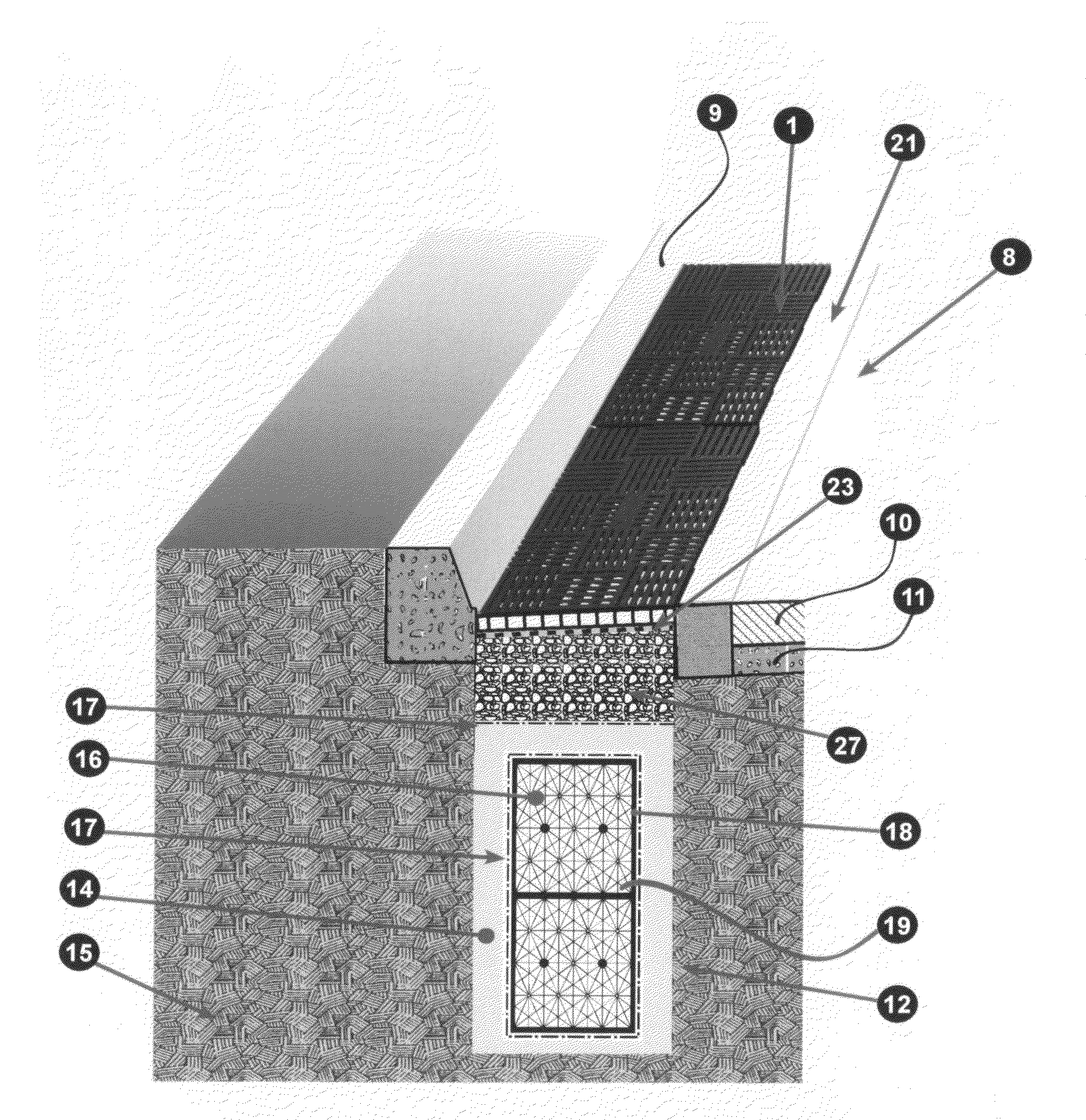
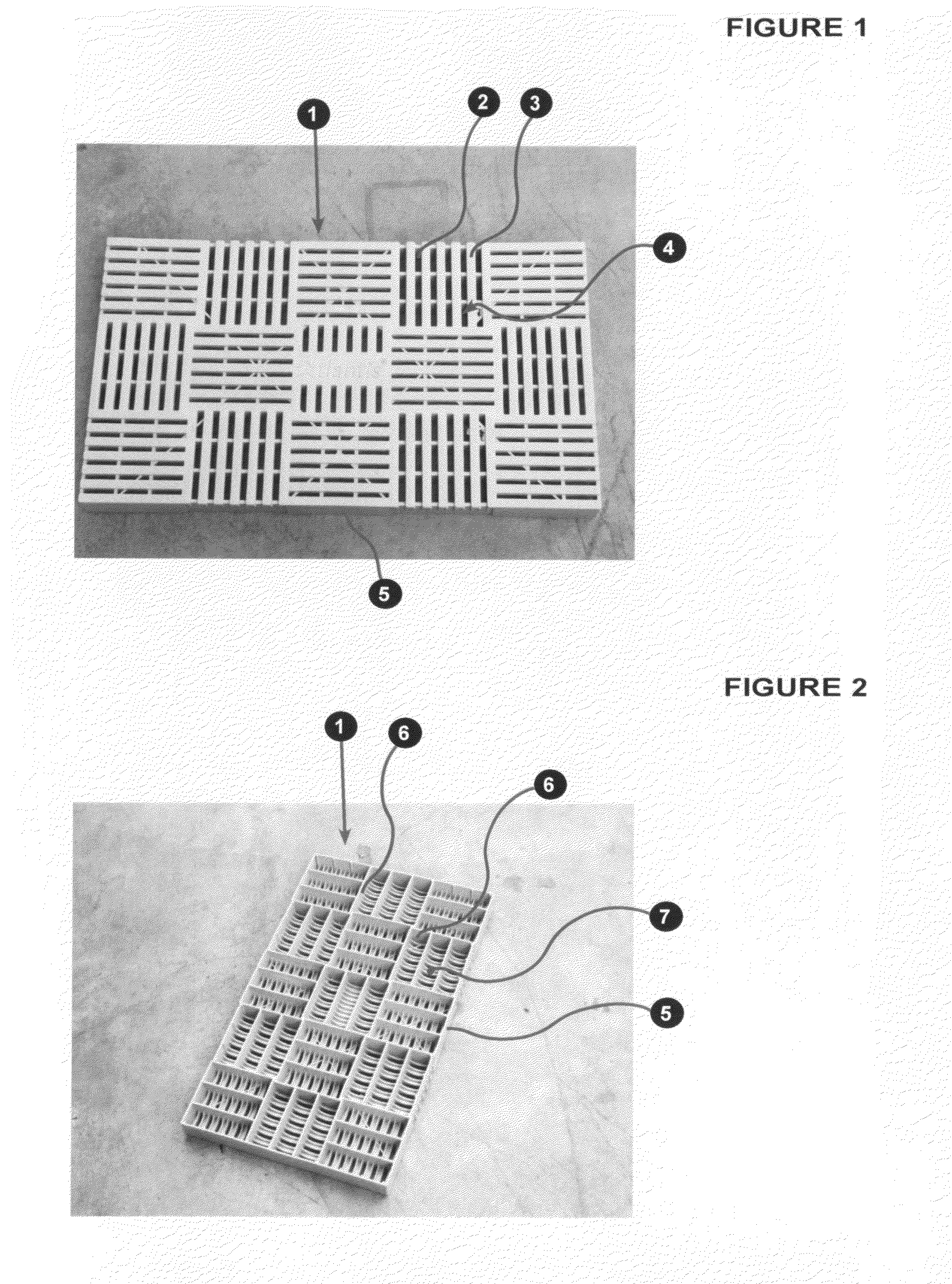
[0030]The grid structure could have the alternating openings and support members of any suitable shapes. However a first embodiment of a grid structure (1) suitable for use with the present invention, as shown in FIGS. 1 & 2, comprises basically an array (4) of alternate parallel elongated openings (2) and support members (3), which form a filter to allow water to pass therethrough while filtering out solids over a predetermined dimension. However preferably as shown the FIGS. 1 & 2, the grid structure (1) has a plurality of arrays (4) which are orientated normal to adjacent arrays (4), such that the elongated openings (2) and support members (3) of one array (4) runs 90° to those of adjacent arrays (4). The elongated opening (2), preferably, has a width less than 10 mm and the support members preferably have a width of approximately 10 mm.

[0031]The grid structure (1) has a peripheral skirt (5) extending below the arrays (4) with web members (6) running transversely across the base ...


PUM


Abstract

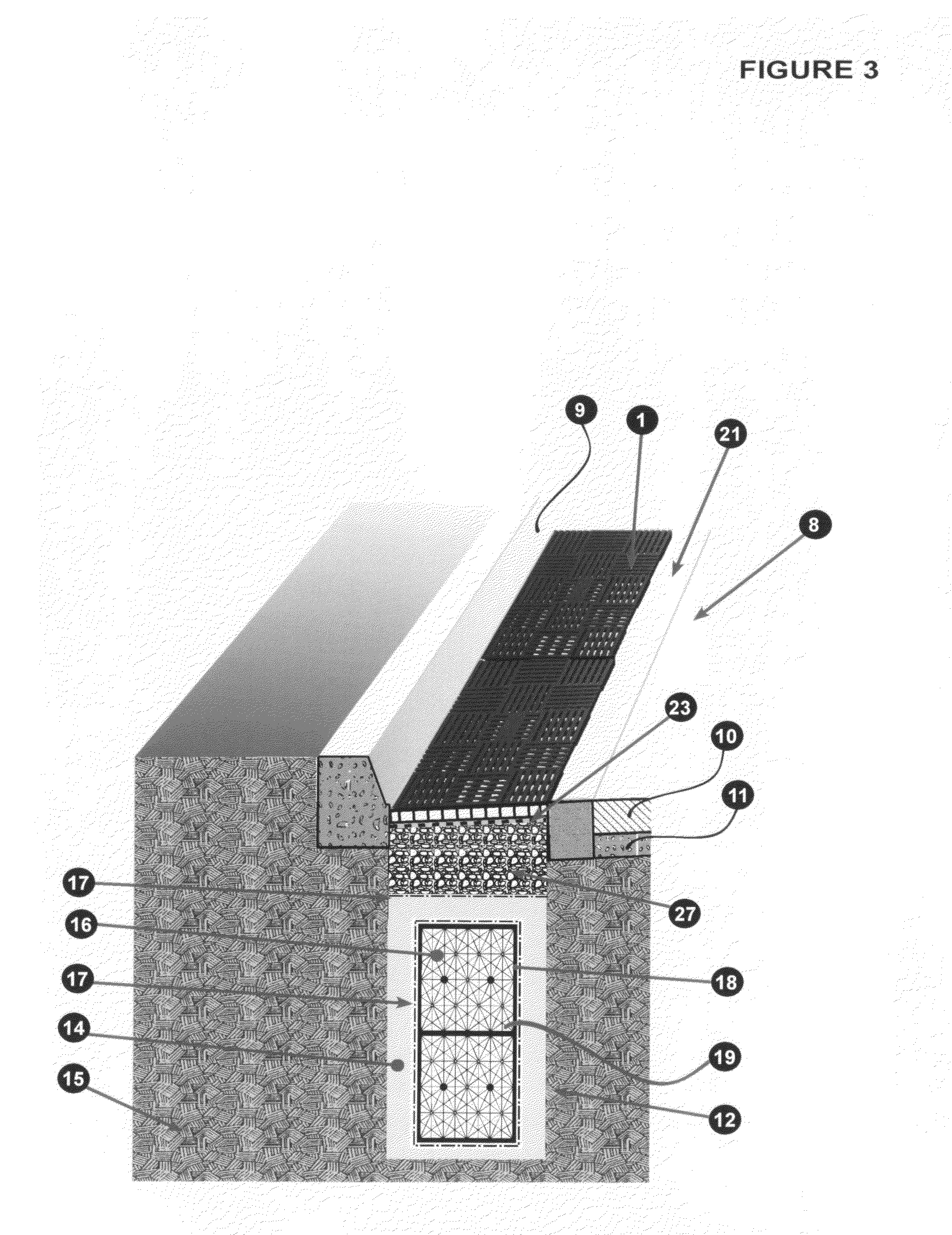
A roadway or other transport corridor infiltration system which collects runoff while allowing for the easily removal of litter from its surface. The infiltration system comprises at least the edge surface of the roadway or other transport corridor being formed by a plastics grid structure having at least its upper surface formed by an array of alternate openings and support members, such that water can permeate therethrough. An infiltration layer is located at least below and in communication with said grid structure, filled with aggregate material, which is larger in cross-section than the width of the openings of said grid structure. A geotextile wrapped water permeable infiltration tank located below and in communication with said infiltration layer, such that runoff passes through the grid structure into the infiltration layer and into the permeable infiltration tank, where the water is stored and / or flows back into the soil through the walls of the tank and the geotextile.

Description

BACKGROUND OF THE INVENTION[0001]The present invention relates to an improved infiltration system for traffic areas such as roadways, train corridors, runways and carparks.[0002]Presently the roadways are based upon the old Roman system of having a water impervious top layer that directs water into side gutters where it passes into underground pipes and drains, which are impervious to water, and is directed from a large catchment area into creeks, rivers and the ocean.[0003]Thus when it rains, all of the rubbish and pollution such as oil, grease, vegetation, dog faeces, food stuffs, paper, dissolved pollutants and detergents, are flushed into the drainage system and concentrated into the outfall area, such as a creek, river and the ocean. There is little or no attempt in most of the existing drainage systems to decontaminate this storm water pollution. If any treatment is carried out, it, usually, only involves a filtering out of larger solids. This dumping of the stormwater runoff ...

Claims


Application Information

Patent Timeline
Patent Type & Authority Patents(United States)
IPC IPC(8): E01F5/00
CPCE01C11/225E01C11/228Y02A10/30Y02A30/30
Inventor URRIOLA, HUMBERTO
Owner ASTRAL PROPERTY
Learn More