Anti-recoil catheter

a catheter and anti-recoil technology, applied in the field of catheters, can solve the problems of increasing the risk of catheter damage, and causing the catheter to be pushed back or to recoil, so as to reduce the trauma of patients and less invasive

Inactive Publication Date: 2010-03-30
ACIST MEDICAL SYST
View PDF85 Cites 32 Cited by
  • Summary
  • Abstract
  • Description
  • Claims
  • Application Information

AI Technical Summary

Benefits of technology

[0015]A further object of the present invention is to provide a small diameter catheter assembly that allows for the management of fluid forces to stabilize the distal tip over a wide range of injection parameters.
[0016]A further object of the present invention is to provide a catheter that is less invasive and reduces patient trauma.
[0017]These and other objects not specifically enumerated herein are believed to be addressed by the present invention which contemplates a catheter assembly comprising a hub section located at a proximal end of the catheter, a shaft section attached to the distal end of the hub, a stem section that is connected to the distal end of the shaft, and a distal tip section attached to the distal end of the stem section. In addition, the catheter assembly also includes a plurality of openings located in the stem and tip sections that provide proper balancing of fluid forces as the fluid exits the openings of the catheter.
[0018]A further object of the present invention is to provide a catheter for use in performing a medical procedure comprising an elongated tubular structure having a proximal end and a distal end. The tubular structure is configured to be a size of no greater than about 4 French and is designed to accommodate fluid flow rates in a range of approximately 0 to 40 ml/sec, and pressures ...

Problems solved by technology

However, the fluid dynamics associated with some catheter designs often cause the catheter to be pushed back or to recoil as a result of the velocity of the fluid as it exits the distal tip.
Such undesirable recoil movement is particularly acute when using a catheter of small size, e.g. less than about 4 French, since these catheters experience particularly high fluid exit velocities due to the flow requirements in a typical angiographic procedure.
However, even larger catheters may be prone to higher recoil if fluid flow out of the tip is of sufficient velocity.
Overall, however, smaller angiographic catheters are more prone to severe whipping and recoil at the outset of an injection than catheters of a larger size.
However, it has been discovered that these catheter designs do not adequately address problems with catheter recoil within the vessel or bo...

Method used


Image

  • Anti-recoil catheter
  • Anti-recoil catheter
  • Anti-recoil catheter

Examples


Embodiment Construction

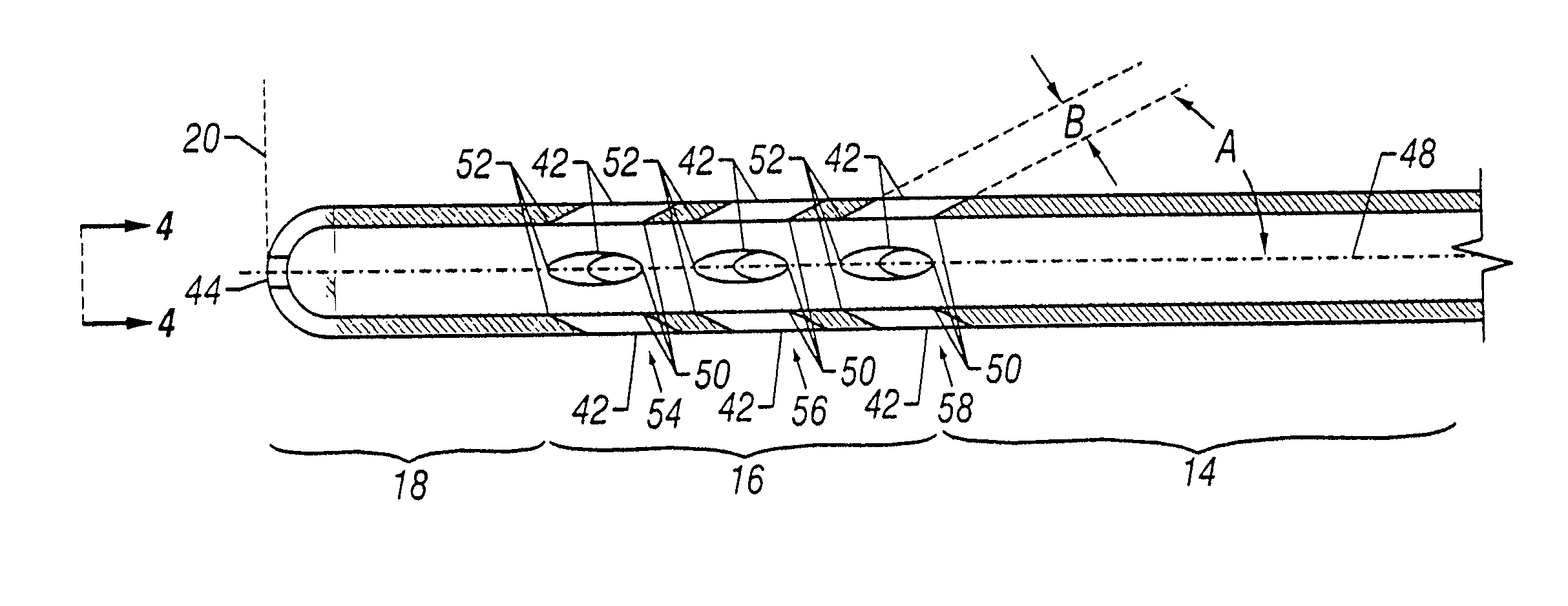
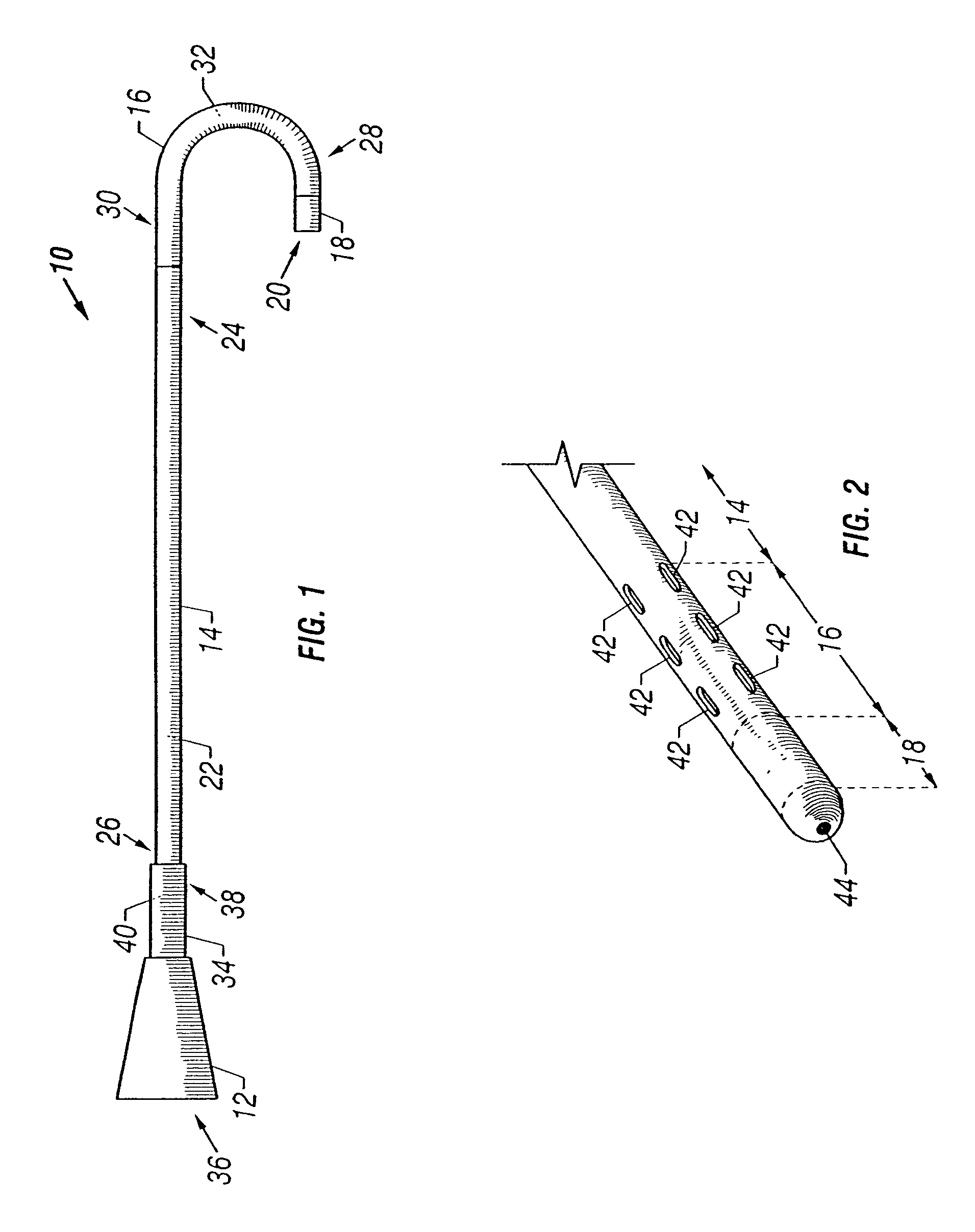
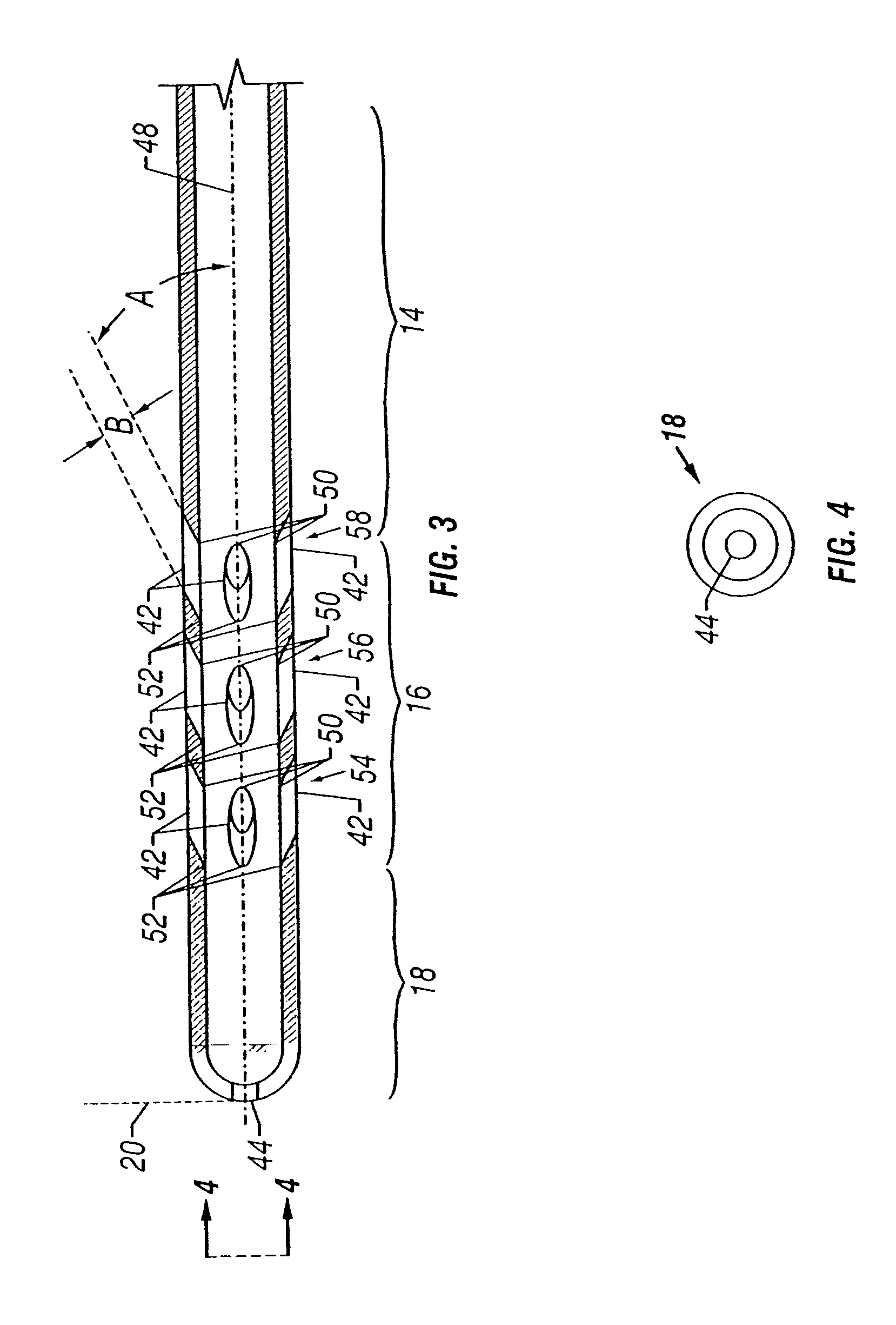
[0039]Referring to FIG. 1, an embodiment of a conventional catheter 10, such as a diagnostic catheter used during angiography or other procedures, in accordance with the present invention includes four major sections including a hub 12, shaft 14, stem 16 and tip 18. The entire length of the catheter assembly 10, including the four major sections, has a maximum external or outside diameter of approximately 4 French. As discussed in greater detail below, the tip configuration in combination with the small size of the catheter diameter results in a catheter having improved management of fluid forces that better stabilize the distal tip 20 of the catheter 10 over a wide range of injection parameters.

[0040]As shown in FIG. 1, the majority of the catheter 10 comprises the shaft portion 14 which includes a central lumen 22, a distal end 24 and a proximal end 26. The through lumen 22 of the shaft 14 communicates with the tip 18 for passage of devices or fluids. Attached to the proximal end ...


PUM


Abstract

A design is disclosed for a catheter assembly used during interventional and/or diagnostic procedures. The catheter includes a plurality of openings that allow for controlled fluid flow as the fluid exits the lumen of the catheter and can be inserted into the vascular system over a guidewire. As a result, the openings balance the fluid forces and, thereby, stabilize the distal tip to accommodate a wide range of injection parameters. The particular design of the catheter assembly of the present invention also reduces and/or eliminates recoil of the catheter tip during high volume injections, such as those associated with coronary or ventricular angiography.

Description

RELATED APPLICATIONS[0001]This application is a continuation of U.S. patent application Ser. No. 09 / 479,110, filed Jan. 7, 2000 now U.S. Pat. No. 6,669,679.FIELD OF THE INVENTION[0002]The present invention relates to catheters used during interventional and / or diagnostic procedures for delivering fluids into a patient. The present invention particularly relates to an angiographic catheter having controlled fluid flow properties for delivering fluids, such as contrast media, into a human or animal body.BACKGROUND OF THE INVENTION[0003]Catheters are commonly used in the diagnosis and treatment of various medical conditions and advancements in catheter designs and materials have made them particularly well-suited for intravascular procedures and intravascular therapies. A conventional catheter includes a small, elongated tube made of flexible, biocompatible materials that enable the catheter to be easily maneuvered through body passages and vascular structures. During an angiographic p...

Claims


Application Information

Patent Timeline
IPC IPC(8): A61M25/00A61M25/16
CPCA61M25/007
Inventor SAVAGE, STEVENBRUCKER, GREGDUCHON, DOUGLAS J.
Owner ACIST MEDICAL SYST
Why Eureka
Try Eureka