
Synthetic jet and method of making same

a technology of synthetic jets and jets, which is applied in the direction of insulated conductors, power cables, cables, etc., can solve the problems of thermal management issues that are presenting an increasing challenge in microelectronics applications, the process is typically limited, and the heat source and ambient environment are high thermal resistan

Inactive Publication Date: 2010-03-30
GENERAL ELECTRIC CO
View PDF16 Cites 34 Cited by
  • Summary
  • Abstract
  • Description
  • Claims
  • Application Information

AI Technical Summary

Benefits of technology

[0008]Embodiments of the invention provide a method and apparatus that overcome the aforementioned drawbacks. Embodiments of the invention are directed method and apparatus for cooling one or more electronic components using a synthetic jet.

Problems solved by technology

The process is typically limited because of the limited opportunity for convection cooling within the housing and over the printed circuit boards.
The low thermal conductivity of the fiberglass epoxy resin-based printed circuit boards can lead to high thermal resistance between the heat source and the ambient environment.
And, with the advent of smaller enclosures, higher digital clock speeds, greater numbers of power-emitting devices, higher power-density components, and increased expectations for reliability, thermal management issues present an increasing challenge in microelectronics applications.
In some applications, cooling opportunities using synthetic jets may be limited because of excess power density in a small device such as a reflector in a lighting application.
However, in such applications, space limitations may preclude placement and use of conventional synthetic jets.
Likewise, in other applications the heated source may be non-planar and complex / curvaceous in shape leading to a non-optimal heat transfer performance with the use of conventional synthetic jets.
Further, a synthetic jet may produce undesirable levels of acoustic noise during operation.
The effect is due to the air in the synthetic jet volume acting as a spring and may be accompanied by a loud tonal noise and a determined vibrational mode if the two modes are not separated from one another in the frequency domain.
Thus, the process of operating a synthetic jet typically results in an acoustically loud noise that may limit or preclude its use in cooling and other applications.

Method used


Image

  • Synthetic jet and method of making same
  • Synthetic jet and method of making same
  • Synthetic jet and method of making same

Examples


Embodiment Construction

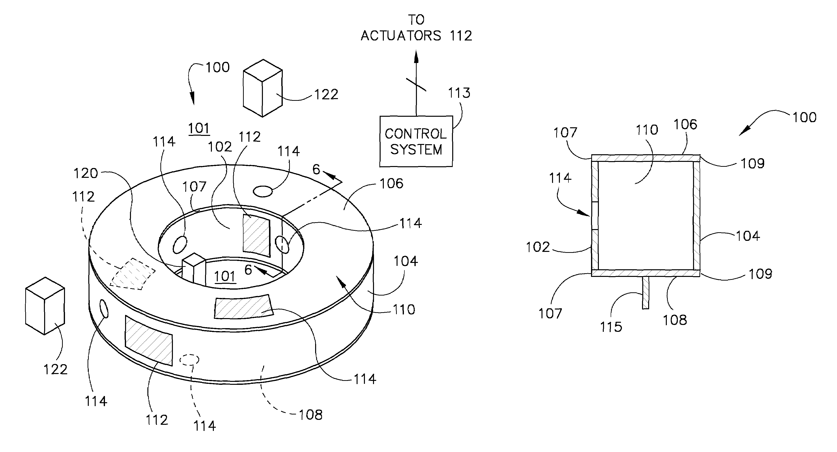
[0022]Embodiments of the invention relate to a piezoelectric motive device and methods of making and using a piezoelectric motive device to reduce the acoustic noise emitting therefrom. The operating environment is described with respect to a thermal management system for enhancing convection in cooling of electronics. However, it will be appreciated by those skilled in the art that embodiments of the invention are equally applicable for use with other synthetic jet applications. For instance, synthetic jets have been routinely used for stand-point flow control, thrust vectoring of jets, triggering turbulence in boundary layers, and other heat transfer applications. Heat transfer applications may include direct impingement of vortex dipoles on heated surfaces and employing synthetic jets to enhance the performance of existing cooling circuits. Thus, although embodiments of the invention are described with respect to cooling of electronics, they are equally applicable to systems and ...


PUM

PropertyMeasurementUnit
volumeaaaaaaaaaa
geometric shapeaaaaaaaaaa
shape-aaaaaaaaaa

Abstract

A synthetic jet includes an inner wall configured to surround a heat-generating component, a plurality of walls coupled to the inner wall, the inner wall and the plurality of walls configured to enclose a volume surrounding the inner wall, an actuator coupled to one of the plurality of walls and the inner wall. The inner wall has a plurality of orifices formed therein configured to direct a fluid toward the heat-generating component upon activation of the actuator.

Description

BACKGROUND OF THE INVENTION[0001]The invention relates generally to synthetic jets and, more particularly, to a method and apparatus of acoustic noise reduction therein.[0002]A synthetic jet may influence the flow over a surface to control flow, as in, for example, separation from an airfoil, or to enhance convection on a surface. A typical synthetic jet actuator includes a housing defining an internal chamber, and an orifice is present in a wall of the housing. The actuator further includes a mechanism in or about the housing for periodically changing the volume within the internal chamber so that a series of fluid vortices are generated and projected in an external environment out from the orifice of the housing. Various volume changing mechanisms include, for example, a piston positioned in the jet housing to move so that gas or fluid is moved in and out of the orifice during reciprocation of the piston and a flexible diaphragm as a wall of the housing. The flexible diaphragm is ...

Claims


Application Information

Patent Timeline
Patent Type & Authority Patents(United States)
IPC IPC(8): H05K7/20
CPCF15D1/00H01L23/467Y10T29/49401H01L2924/0002H01L2924/00
Inventor ARIK, MEHMETUTTURKAR, YOGEN VISHWAS
Owner GENERAL ELECTRIC CO
Features
  • Generate Ideas
  • Intellectual Property
  • Life Sciences
  • Materials
  • Tech Scout
  • Unparalleled Data Quality
  • Higher Quality Content
  • 60% Fewer Hallucinations
Learn More