All-digital phase modulator/demodulator using multi-phase clocks and digital PLL

a digital phase modulator and digital pll technology, applied in the field of electronic signal transmission, can solve the problem that analog components are difficult to integrate with large digital system chips

Inactive Publication Date: 2010-03-30
KINGSTON DIGITAL CO LTD
View PDF3 Cites 64 Cited by
  • Summary
  • Abstract
  • Description
  • Claims
  • Application Information

AI Technical Summary

Problems solved by technology

However, these analog components are difficult to integrate with large digital system chips.

Method used


Image

  • All-digital phase modulator/demodulator using multi-phase clocks and digital PLL
  • All-digital phase modulator/demodulator using multi-phase clocks and digital PLL
  • All-digital phase modulator/demodulator using multi-phase clocks and digital PLL

Examples


Embodiment Construction

[0022]The present invention relates to an improvement in signal modulators. The following description is presented to enable one of ordinary skill in the art to make and use the invention as provided in the context of a particular application and its requirements. Various modifications to the preferred embodiment will be apparent to those with skill in the art, and the general principles defined herein may be applied to other embodiments. Therefore, the present invention is not intended to be limited to the particular embodiments shown and described, but is to be accorded the widest scope consistent with the principles and novel features herein disclosed.

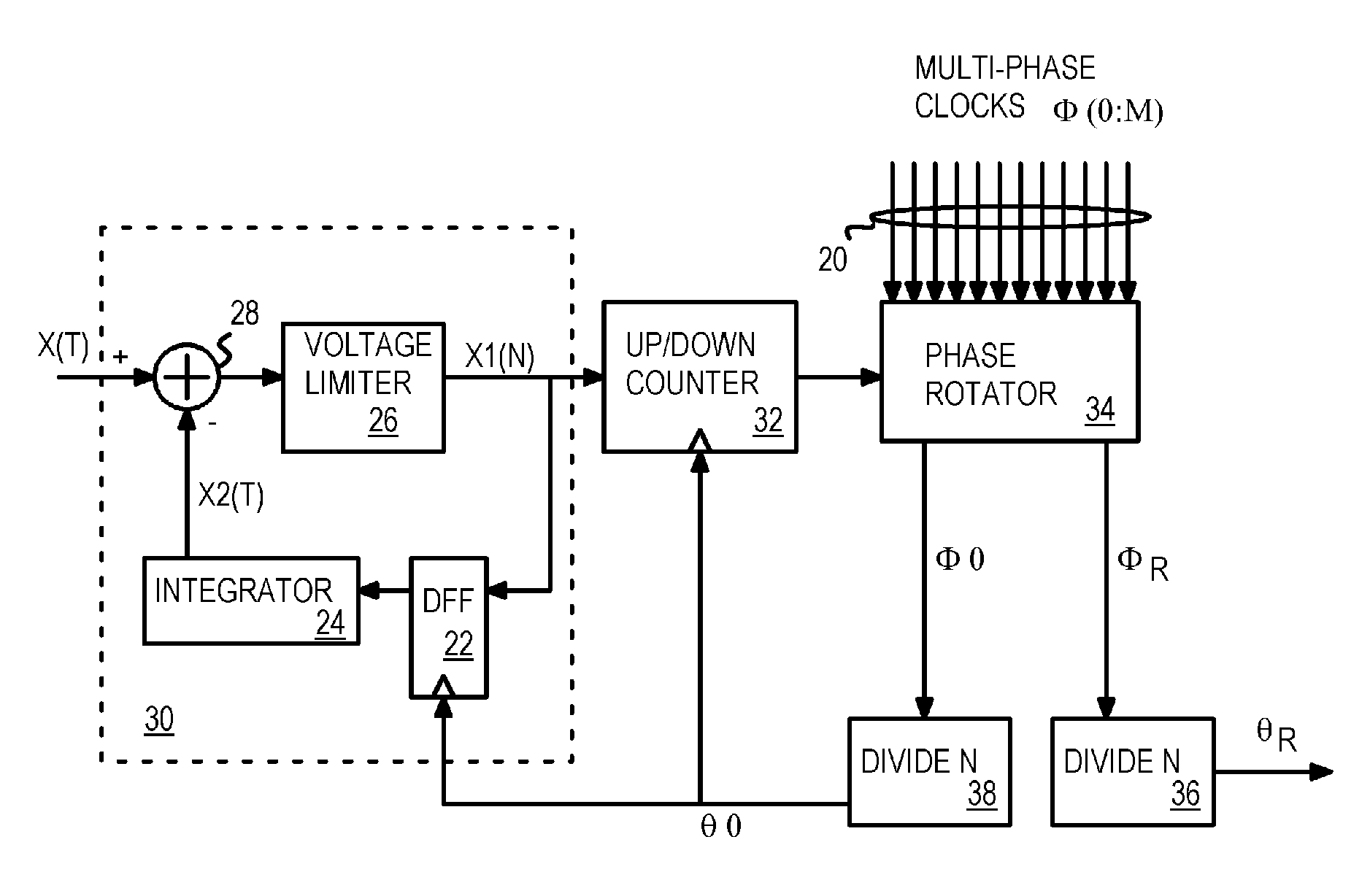
[0023]FIG. 3 is a block diagram of a modulator using multi-phase clocks with an analog-front end. Analog front end 30 receives analog input x(t) that is an input signal to be modulated. The modulated output is modulated carrier θR generated from rotated clock φR from phase rotator 34.

[0024]Analog front end 30 outputs digital signal ...


PUM


Abstract

Multi-phase clocks are used to encode and decode signals that are phase-modulated. The input signal is phase-compared with a feedback clock. Phase differences increment or decrement an up / down counter. The count value from the up / down counter is applied to a phase rotator, which selects one clock phase from a bank of multi-phase clocks. The multi-phase clocks have the same frequency, but are offset in phase from each other. An output divider divides the selected multi-phase clock to generate a phase-modulated output. A feedback divider divides a fixed-phase clock from the multi-phase clocks to generate the feedback clock. An analog or a digital front-end may be used to convert analog inputs to digital signals to increment or decrement the counter, or to encode multiple digital bits as phase assignments. For a de-modulator, a digital-to-analog converter (DAC) or a digital decoder produces the final output from the count of the up / down counter.

Description

RELATED APPLICATION[0001]This application is a continuation of Ser. No. 10 / 249,335, now U.S. Pat. No. 7,221,727.FIELD OF THE INVENTION[0002]This invention relates to electronic signal transmission, and more particularly to using all-digital Phase-locked loops (PLL's) in modulators and demodulators.BACKGROUND OF THE INVENTION[0003]Digital implementations of phase-locked loops (PLL's) are widely used in various applications, such as digital communications and clock / data recovery. Conventional implementations of digital phase-locked loops normally use a numerically controlled oscillator (NCO) as the frequency source. An NCO (also known as a digitally controlled oscillator or DCO), particularly one implemented as counter, suffers from phase resolution or frequency granularity at high frequency.[0004]Another type of digital PLL uses a set of multi-phase clocks rather than a variable-frequency oscillator. Using Multi-phase clocks can improve the phase resolution of digitally implemented o...

Claims


Application Information

Patent Timeline
Patent Type & Authority Patents(United States)
IPC IPC(8): H03D3/24H03C3/09H03L7/081H04L27/22
CPCH03C3/0966H03L7/0814H04L27/22H03L2207/50H03C3/00H03C3/09
Inventor CO, RAMON S.
Owner KINGSTON DIGITAL CO LTD
Why Eureka
Try Eureka