Frequency selective passive component networks for implantable leads of active implantable medical devices utilizing an energy dissipating surface

a passive component and active technology, applied in the field of energy induced into implantable leads, can solve the problems of low temperative rise, high electrical field around the instrument, and local tissue heating

Inactive Publication Date: 2010-03-30
WILSON GREATBATCH LTD
View PDF38 Cites 95 Cited by
  • Summary
  • Abstract
  • Description
  • Claims
  • Application Information

AI Technical Summary

Benefits of technology

[0026]The '725 Provisional Application explains the need to cut / remove the electrodes from the circuit in the MHz frequency range. This is accomplished with the inductor circuit elements. In the MHz frequency range, the surface ring electrodes are not connected to the rest of the electrical leads. Therefore, the ends of the leads are now buried inside of the catheter. The coupled high electric fields will now be located inside of the catheter instead of in the tissue. This results in significant reduction and unwanted tissue heating.
[0027]In the '725 Provisional Application, the inside of the catheter, of course, includes a body with a specific thermal mass and specific thermal properties. Over time, it will rise in temperature and therefore heat surrounding body tissue. However, this temperative rise is minimal due to the large area and thermal mass of the catheter which acts as an energy dissipating area or surface. Also, any such minimal heating that does occur is in body tissue in an area that is distant from the therapy electrode(s). Therefore, the ability for the pacing or stimulus electrode to delivery energy in the proper location will not be compromised. By spreading the RF energy over a larger surface area (i.e. inside the catheter) the temperature rise is therefore reduced and the resulting small amount of heat is generally dissipated into bulk body tissues instead of at a specific point.

Problems solved by technology

This results in high electrical fields around the instrument and local tissue heating.
However, this temperative rise is minimal due to the large area and thermal mass of the catheter which acts as an energy dissipating area or surface.

Method used


Image

  • Frequency selective passive component networks for implantable leads of active implantable medical devices utilizing an energy dissipating surface
  • Frequency selective passive component networks for implantable leads of active implantable medical devices utilizing an energy dissipating surface
  • Frequency selective passive component networks for implantable leads of active implantable medical devices utilizing an energy dissipating surface

Examples


Embodiment Construction

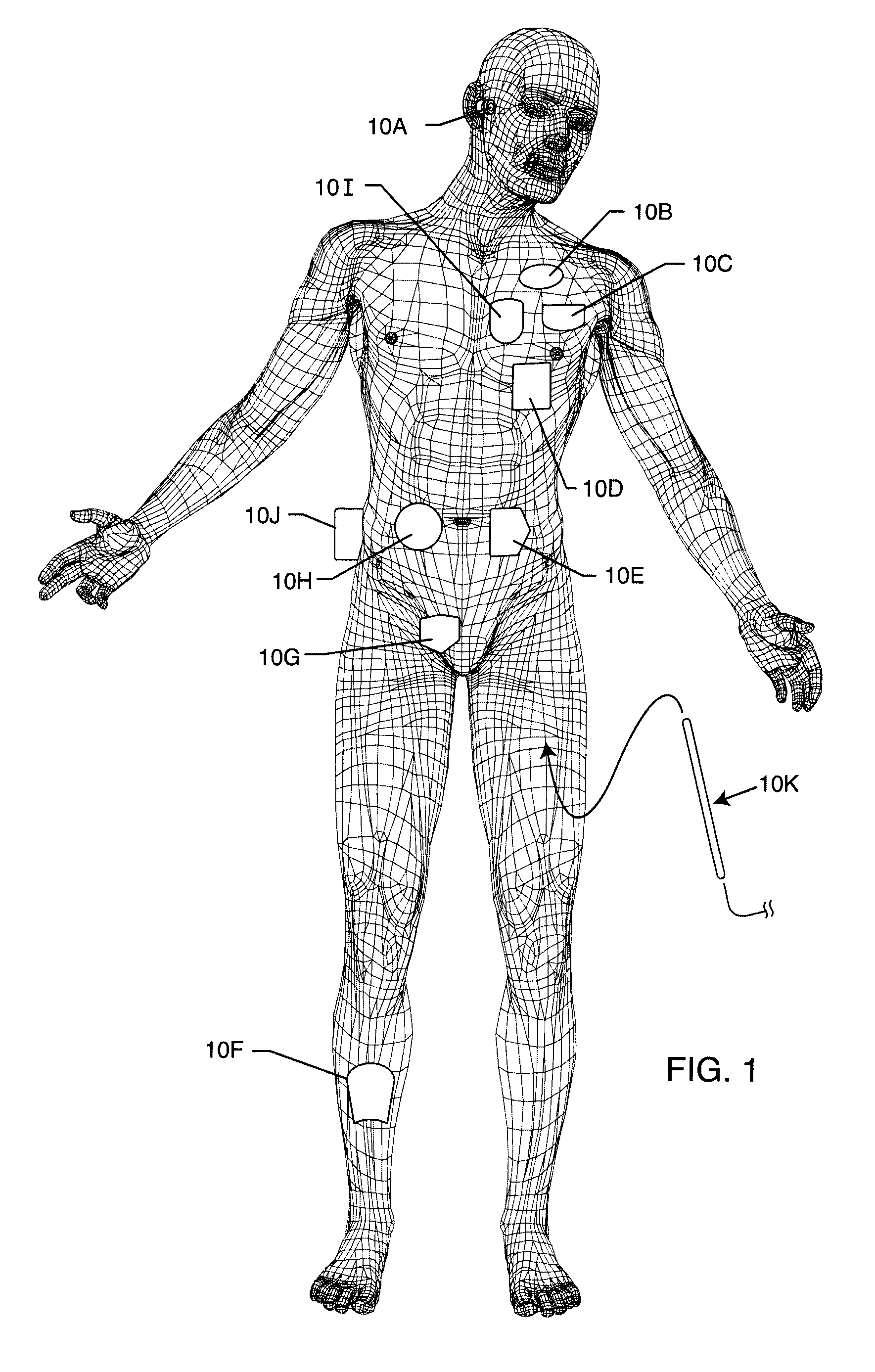
[0119]FIG. 1 illustrates various types of active implantable medical devices referred to generally by the reference numeral 10 that are currently in use. FIG. 1 is a wire formed diagram of a generic human body showing a number of exemplary implanted medical devices. 10A is a family of implantable hearing devices which can include the group of cochlear implants, piezoelectric sound bridge transducers and the like. 10B includes an entire variety of neurostimulators and brain stimulators. Neurostimulators are used to stimulate the Vagus nerve, for example, to treat epilepsy, obesity and depression. Brain stimulators are similar to a pacemaker-like device and include electrodes implanted deep into the brain for sensing the onset of the seizure and also providing electrical stimulation to brain tissue to prevent the seizure from actually happening. 10C shows a cardiac pacemaker which is well-known in the art. 10D includes the family of left ventricular assist devices (LVAD's), and artifi...


PUM


Abstract

Decoupling circuits are provided which transfer energy induced from an MRI pulsed RF field to an energy dissipating surface. This is accomplished through broadband filtering or by resonant filtering. In a passive component network for an implantable leadwire of an active implantable medical device, a frequency selective energy diversion circuit is provided for diverting high-frequency energy away from a leadwire electrode to a point or an area spaced from the electrode, for dissipation of high-frequency energy.

Description

BACKGROUND OF THE INVENTION[0001]This invention generally relates to the problem of energy induced into implanted leads during medical diagnostic procedures such as magnetic resonant imaging (MRI). Specifically, the radio frequency (RF) pulsed field of MRI can couple to an implanted lead in such a way that electromagnetic forces (EMFs) are induced in the lead. The amount of energy that is induced is related to a number of complex factors, but in general, is dependent upon the local electric field that is tangent to lead and the integral of the tangential electric field strength along the lead. In certain situations, these EMFs can cause currents to flow into distal electrodes or in the electrode interface with body tissue. It has been documented that when this current becomes excessive, that overheating of said electrode or overheating of the associated interface with body tissue can occur. There have been cases of damage to such body tissue which has resulted in loss of capture of ...

Claims


Application Information

Patent Timeline
Patent Type & Authority Patents(United States)
IPC IPC(8): A61N1/08A61B18/14A61B19/00G01R33/28
CPCA61B18/1492A61N1/08G01R33/287A61B2018/00839A61N2001/086A61B2019/5236A61B2090/374A61N1/086A61N1/05
Inventor STEVENSON, ROBERT A.DABNEY, WARREN S.FRYSZ, CHRISTINE A.TRUEX, BUEHL E.HALPERIN, HENRY R.LARDO, ALBERT C.
Owner WILSON GREATBATCH LTD
Why Eureka
Try Eureka