Sensing system

a technology of sensing system and touch system, which is applied in the field of sensing system, can solve the problems of relatively high production cost of each of the touch system disclosed in the patents, and achieve the effect of low production cos

Inactive Publication Date: 2010-03-30
PIXART IMAGING INC
View PDF5 Cites 62 Cited by
  • Summary
  • Abstract
  • Description
  • Claims
  • Application Information

AI Technical Summary

Benefits of technology

[0008]The present invention is directed to provide a sensing system of which the production cost is relatively low.
[0019]The processor of the sensing system of the embodiment of the present invention can calculate the location of the pointer by means of employing the reflective element and the image sensor. Therefore, compared with the conventional arts, the sensing system of the present embodiment can employ one image sensor such that the production cost thereof is low.

Problems solved by technology

Each of the touch systems disclosed in the above two patents must have at least two sensors, such that the production cost of each of the touch systems disclosed in the patents is relatively high.
However, the conventional touch screen system 100 must have the two photosensors 120 and 130, such that the production cost thereof is relatively high.

Method used


Image

  • Sensing system
  • Sensing system
  • Sensing system

Examples


first embodiment

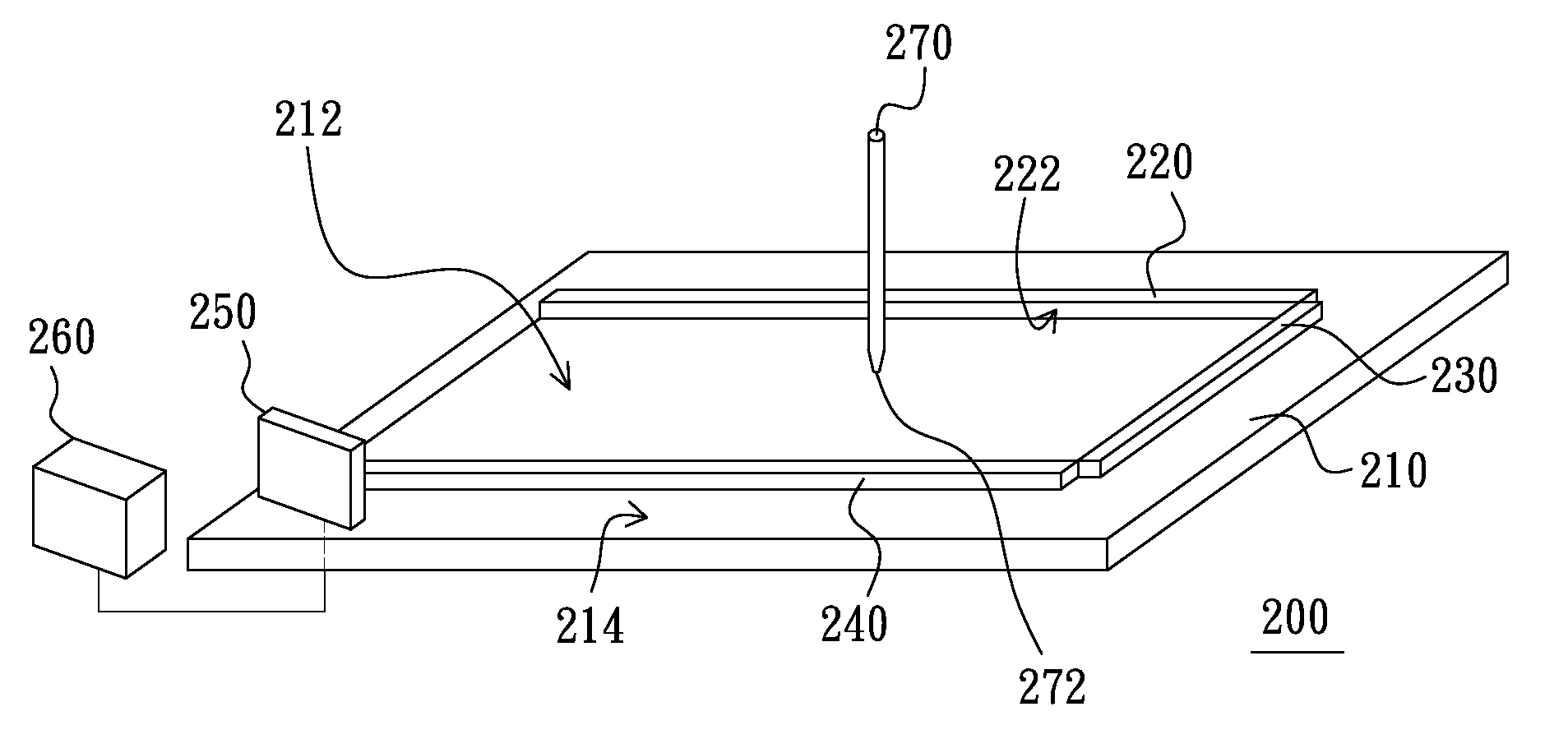
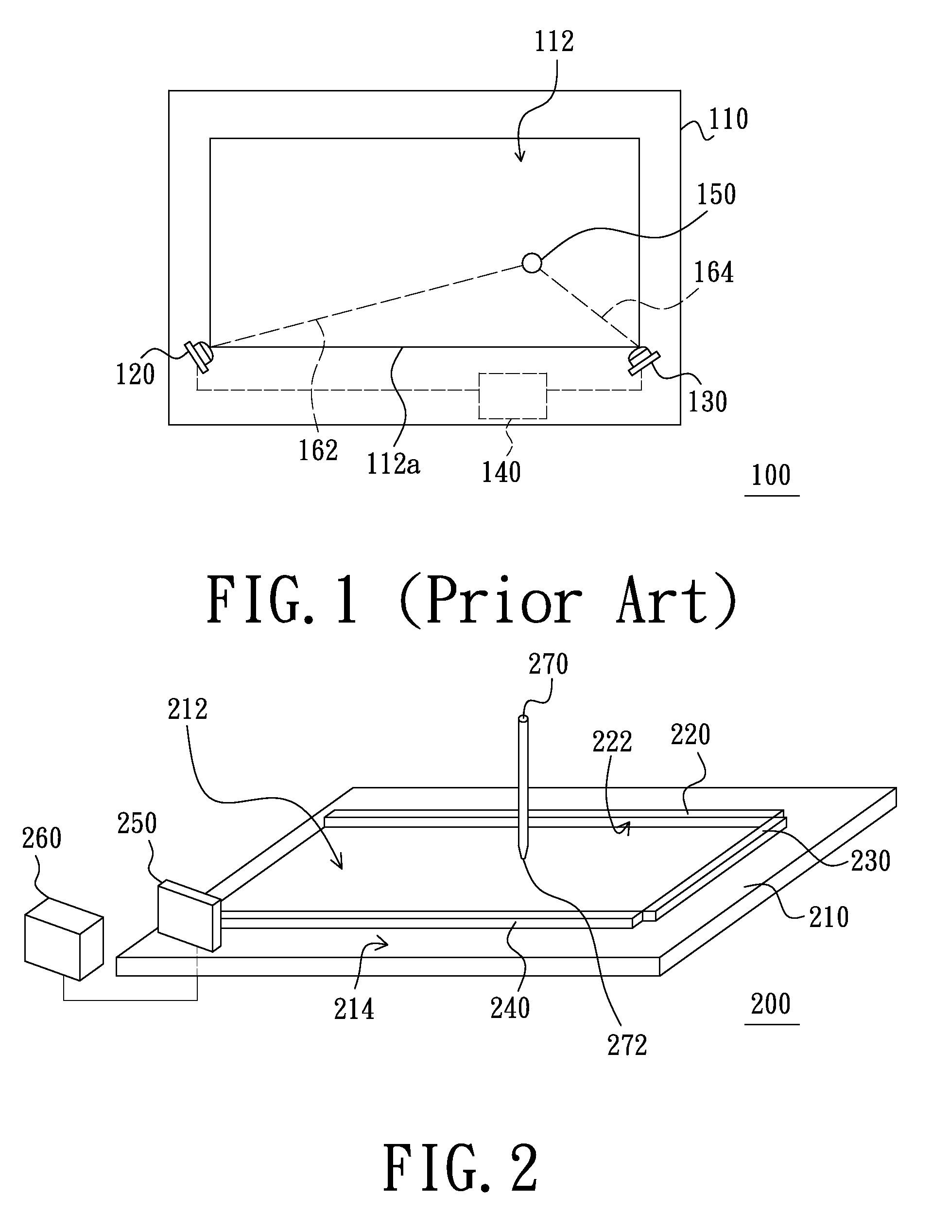
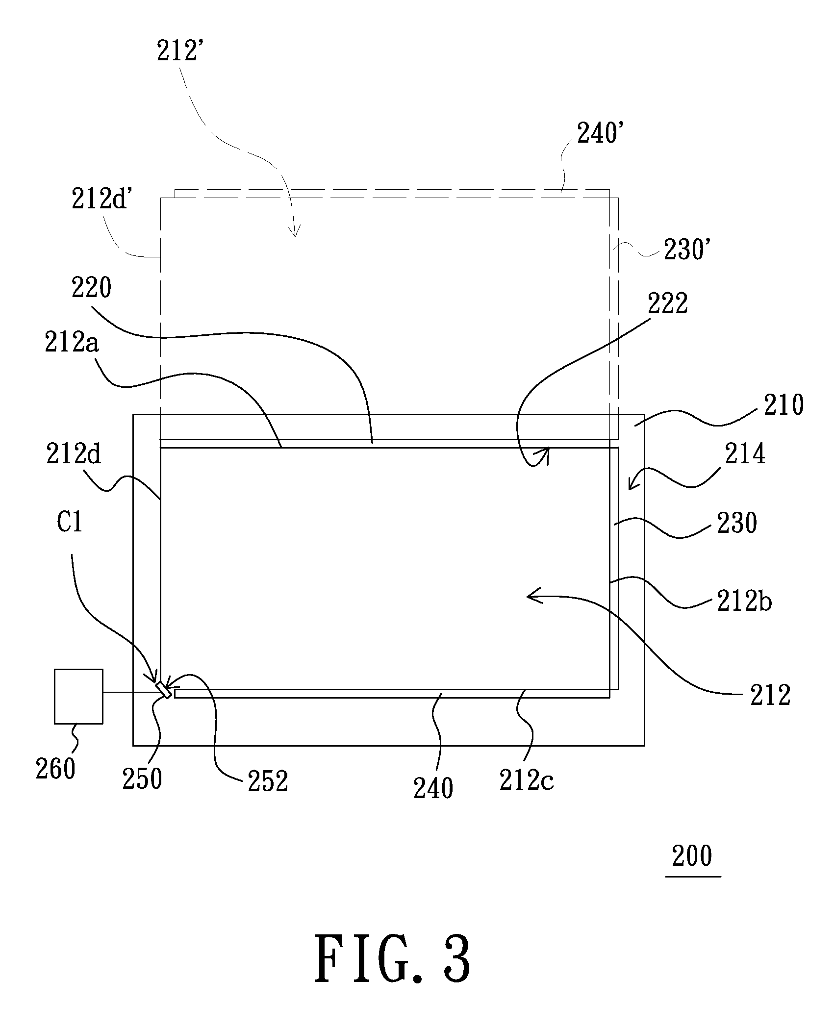
[0033]FIG. 2 is a schematic three-dimensional view of a sensing system of a first embodiment of the present invention. FIG. 3 is a schematic top view of the sensing system of FIG. 2 in operation. Referring to FIGS. 2 and 3, the sensing system 200 is adapted to sense a pointer 270 and calculates the location of the pointer 270 (please see the following detailed description). The sensing system 200 includes a panel 210, a reflective element 220, a first linear light source 230, a second linear light source 240, an image sensor 250 and a processor 260. The panel 210, for example, a whiteboard or a touch screen, have a first plane 214 and a first area 212 located at the first plane 214. The first area 212 is quadrangular, such as a rectangle. Furthermore, the first area 212 has a first boundary 212a, a second boundary 212b, a third boundary 212c and a fourth boundary 212d which are connected in order.

[0034]The reflective element220 is disposed at the first boundary 212a and located on t...

second embodiment

[0043]FIG. 6 is a schematic top view of a sensing system in operation of a second embodiment of the present invention. FIG. 7 is a schematic view showing that the processor of FIG. 6 calculates the location of the pointer. Referring to FIGS. 6 and 7, the difference between the sensing system 300 of the present embodiment and the sensing system 200 of the first embodiment lies in that the present sensing system 300 further includes a third linear light source 390 and that the first area 312 located at the first plane 314 of the panel 310 is quadrangular and not a rectangle.

[0044]The third linear light source 390 is disposed at the fourth boundary 312d of the first area 312, and the third linear light source 390 is mirrored by the reflective element 320 to form a fourth mirror image 390′. The reflective element 320 disposed at the first boundary 312a of the first area 312, the first linear light source 330 disposed at the second boundary 312b of the first area 312, the second linear l...

third embodiment

[0052]FIG. 10 is a schematic three-dimensional view of a sensing system of a third embodiment of the present invention. Referring to FIGS. 2 and 10, the difference between the sensing system 400 and the sensing system 200 lies in that the first linear light source 230 and the second linear light source 240 are omitted in the sensing system 400. The sensing system 400 includes a first light source 430 located above the first plane 414 of the panel 410 and outside the first area 412. The first light source 430 is mirrored by the reflective element 420 to form a second mirror image 430′. The first light source 430 and the second mirror image 430′ are located outside the sensing range of the image sensor 450. The pointer 470 has a reflective surface 472 which may be coated by a reflective material. The reflective material of the reflective surface 472 meets the Europe Standard of EN471 but is not limited in this.

[0053]The first light source 430 is adapted to emit invisible light, such a...


PUM


Abstract

A sensing system is adapted to sense a pointer and calculate a location of the pointer. The sensing system includes a panel, a reflective element, an image sensor and a processor connected to the image sensor. The panel has a first plane and a first area located at the first plane. The first area is quadrangular and has a first boundary, a second boundary, a third boundary and a fourth boundary connected in order. The reflective element is disposed at the first boundary and located on the first plane. A second plane of the reflective element which is a reflective plane is substantially perpendicular to the first plane and mirrors the first area to form a second area. The image sensor sensing the first and the second areas is disposed at a corner at which the third boundary and the fourth boundary intersects and located on the first plane.

Description

BACKGROUND[0001]1. Field of the Invention[0002]The present invention relates to a sensing system, and more particularly, to a sensing system having a reflective element.[0003]2. Description of the Related Art[0004]Touch systems have been disclosed in many patents, such as U.S. Pat. No. 4,782,328 and U.S. Pat. No. 6,803,906. Each of the touch systems disclosed in the above two patents must have at least two sensors, such that the production cost of each of the touch systems disclosed in the patents is relatively high. One of the two patents is described thereinafter in detail.[0005]FIG. 1 is a schematic view of a conventional touch screen system. Referring to FIG. 1, the touch screen system 100 disclosed in the U.S. Pat. No. 4,782,328 includes a panel 110, a first photosensor 120, a second photosensor 130 and a processor 140. The panel 110 has a touch screen area 112 which is a rectangle. The first photosensor 120 and the second photosensor 130 are disposed at two opposite ends of a ...

Claims


Application Information

Patent Timeline
Patent Type & Authority Patents(United States)
IPC IPC(8): G06F15/00G06F3/033G06F3/042
CPCG06F3/0428G06F3/00G06F3/03G06F9/00
Inventor LIN, CHO-YICHENG, HSIN-CHI
Owner PIXART IMAGING INC
Why Eureka
Try Eureka