
Interlock system

a technology of interlocking system and interlocking ring, which is applied in the field of interlocking system, can solve problems such as harm to users, interlocking,

Active Publication Date: 2010-04-06
KENWOOD CO LTD
View PDF6 Cites 17 Cited by
  • Summary
  • Abstract
  • Description
  • Claims
  • Application Information

AI Technical Summary

Benefits of technology

[0004]Preferably, the said pattern comprises a symmetrical distribution of said latch members around a substantially circular path. Such an arrangement provides for secure and well defined latching of receptacles to said housing.

Problems solved by technology

It is well known that domestic electrical appliances incorporating moving parts and / or heating elements that could, under certain operational circumstances, cause harm to a user have interlock systems to protect users by preventing the flow of electric current to the prime mover or heating element when such operational circumstances occur.
Hence difficulties arise in providing interlock systems that are sufficiently robust and reliable to meet user demands and comply with stringent regulatory stipulations, whilst being economical to produce and conforming to an acceptable aesthetic design.

Method used


Image

  • Interlock system
  • Interlock system
  • Interlock system

Examples


Embodiment Construction

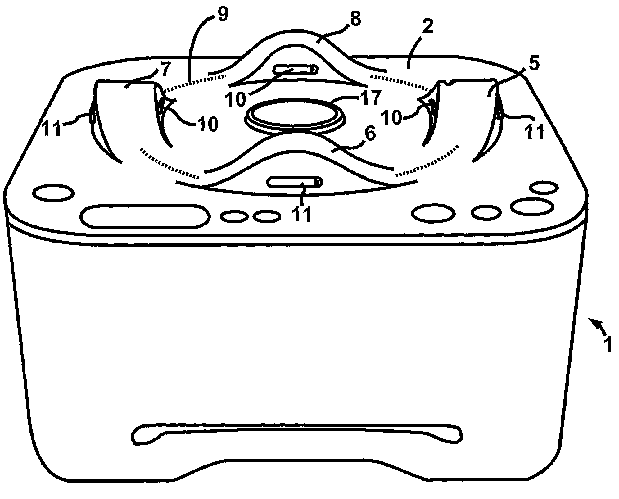
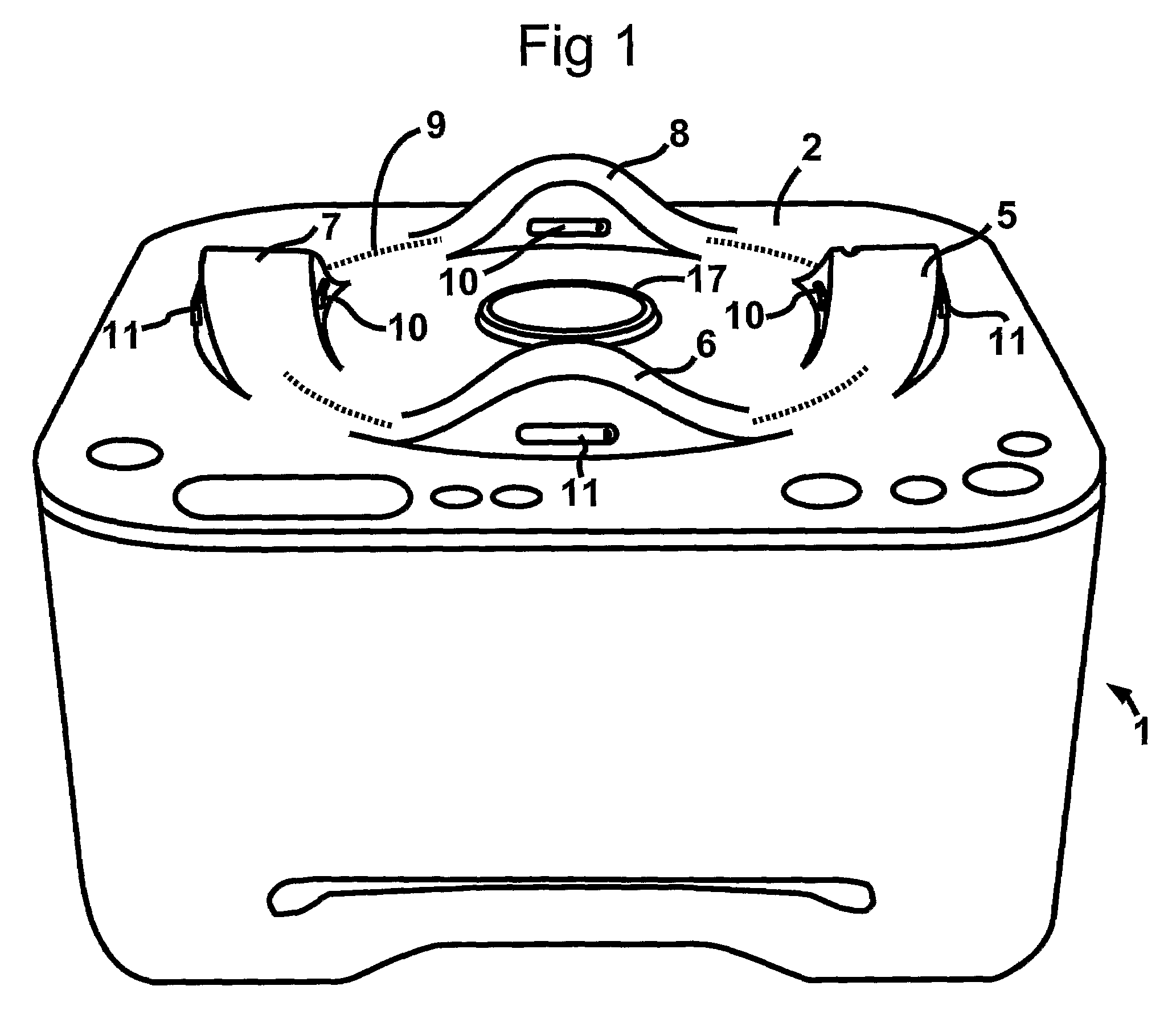
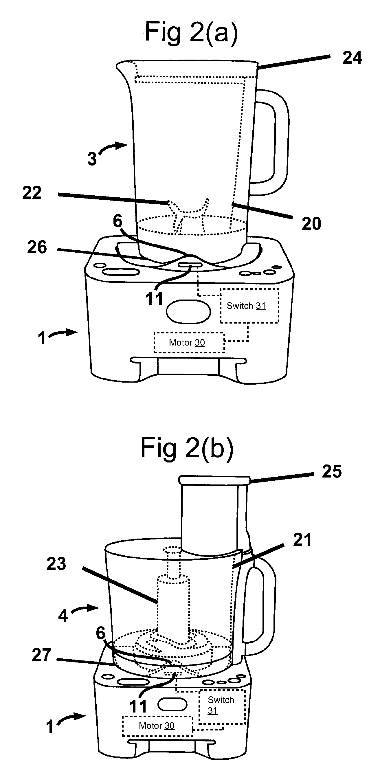
[0018]Referring now to the drawings, one example of the invention provides an interlock system comprising a base housing 1 containing a drive motor 30; the housing 1 presenting a substantially horizontal support surface 2 for goblet-like and bowl-like receptacles such as 3 and 4 respectively (see FIGS. 2(a) and 2(b)); each adapted to contain processing tools (22, 23) intended to be driven in rotation by said motor 30. The support surface 2 supports a plurality of discrete, upstanding latch members 5 to 8, distributed in a predetermined pattern; in this case equally spaced around a notional circular path 9 on the surface 2. Each latch member 5 to 8 contains respective elements such as 10, 11 for temporarily latching to the housing receptacles such as 3 and 4 having bases 26, 27 with base configurations of, in this example, two different and predetermined kinds.

[0019]As can best be seen from FIG. 3, at least one of said latch members 5 presents, by way of first and second apertures 12...


PUM

PropertyMeasurementUnit
electrical currentaaaaaaaaaa
electric currentaaaaaaaaaa
current flowaaaaaaaaaa

Abstract

The invention provides an interlock system whereby operation of a domestic appliance such as a food processor containing an electric motor capable of driving a bladed or similar processing tool at relatively high speed is inhibited unless a vessel having a first or a second base configuration is securely mounted to the appliance so as to contain the tool; the vessel having a lid or cover intended to be in place for safe operation when the processing tool is driven by the motor. A vessel-supporting surface of the appliance carries several up-standing latches, each of which is formed with features capable of co-operating with vessels having either of the base configurations to temporarily latch either type of vessel operationally to the appliance. At least one of the latches is formed with first and second apertures allowing operational access for respective interlock actuators responsive to the lid or cover of a vessel being in place as intended, to an interlock switch whereby electrical current is permitted to flow to the motor only when a vessel having one or other of the different base configurations is latched to the appliance and the vessel is safely closed by its lid or cover.

Description

FIELD OF THE INVENTION[0001]This invention relates to interlock systems, and it relates especially, though not exclusively, to such systems as are intended for use as safety measures for multi-purpose domestic electrical appliances designed for carrying out plural operations such as food processing, food mixing, blending and the like.BACKGROUND OF THE INVENTION[0002]It is well known that domestic electrical appliances incorporating moving parts and / or heating elements that could, under certain operational circumstances, cause harm to a user have interlock systems to protect users by preventing the flow of electric current to the prime mover or heating element when such operational circumstances occur. Thus, interlock systems are an essential feature of many domestic appliances, and their components need to satisfy demanding, and sometimes opposing, regulatory, operational and economic criteria. Hence difficulties arise in providing interlock systems that are sufficiently robust and ...

Claims


Application Information

Patent Timeline
Patent Type & Authority Patents(United States)
IPC IPC(8): B02C17/00A47J43/25A47J43/07
CPCA47J43/0777H01H9/20H01H9/22
Inventor FERRABY, ROBIN
Owner KENWOOD CO LTD
Learn More