Electric machine with a circuit support

a circuit support and electric machine technology, applied in the direction of windings, dynamo-electric components, synchronous machines, etc., can solve the problems of inability to reliably interconnect or properly route the winding ends themselves, and achieve the effect of simplifying the assembly process for interconnecting the wires and preventing mistakes

Active Publication Date: 2010-04-06
SIEMENS AG
View PDF45 Cites 31 Cited by
  • Summary
  • Abstract
  • Description
  • Claims
  • Application Information

AI Technical Summary

Benefits of technology

[0006]It is therefore an object of the invention to provide an electric machine wherein mistakes in interconnecting the windings can be...

Problems solved by technology

These conventional arrangements have the disadvantage that, although the winding ends or the windi...

Method used


Image

  • Electric machine with a circuit support
  • Electric machine with a circuit support
  • Electric machine with a circuit support

Examples


Embodiment Construction

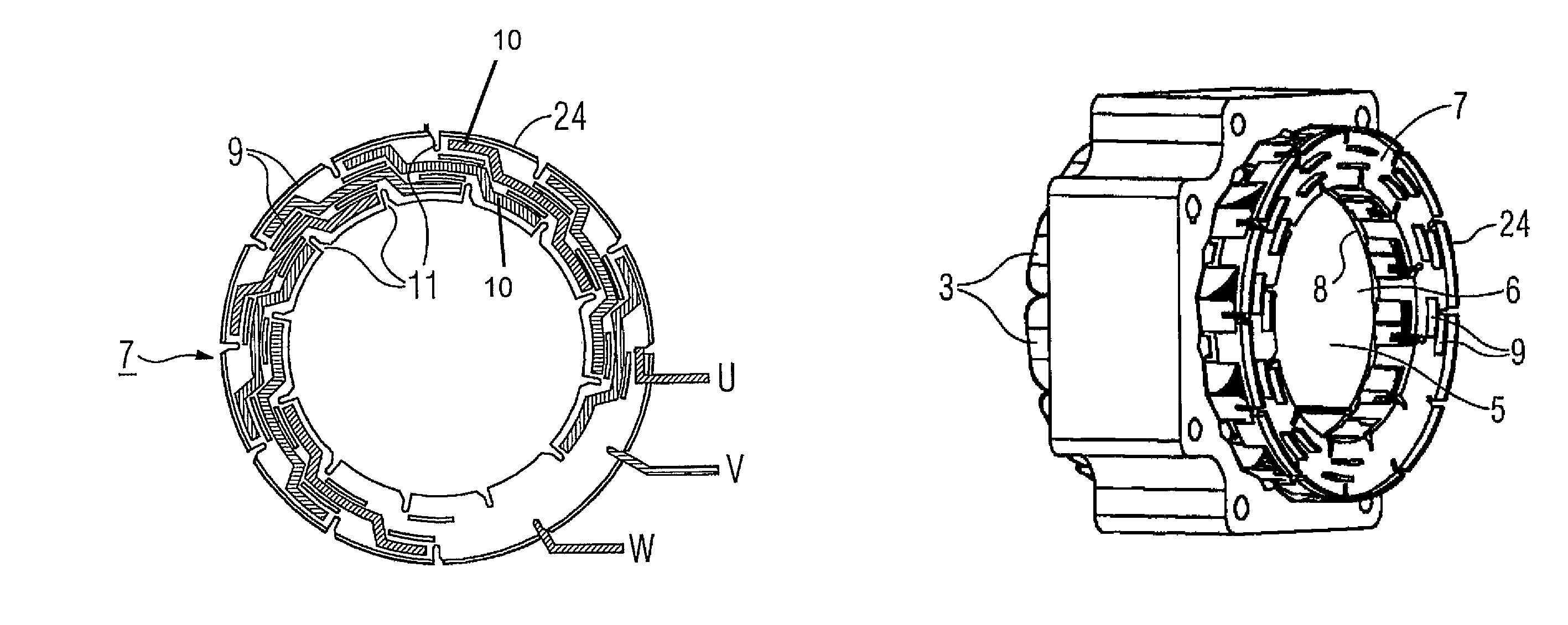
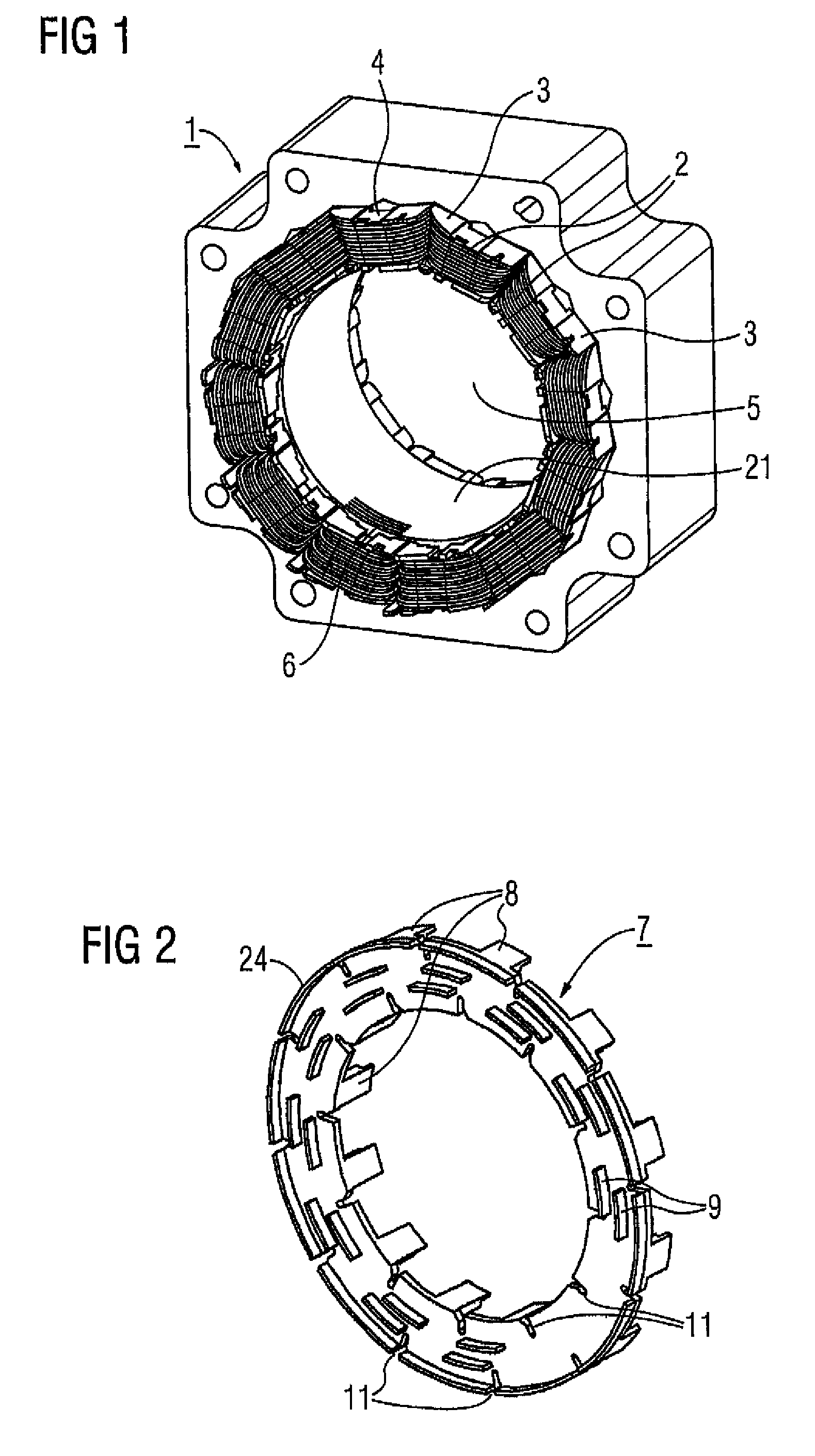
[0047]FIG. 1 shows an electric machine 1 which can advantageously be a servo motor, a torque motor or a generator. The electric machine 1 includes a winding system which in the illustrated example is constructed of toothed coils 2. However, the circuit support arrangement according to the invention can also be used with other winding systems, for example fractional pitch windings, dual-layer windings, and the like.

[0048]The toothed coils 2 are advantageously arranged on a support 3, so that the unit comprised of the toothed coil 2 and the support 3 can be preassembled and later needs only to be placed on the teeth 33 of stator 21 which form the slots 35. As seen in FIGS. 18 and 19, the stator is advantageously split in the axial direction, so that the toothed coil 2 of the support 3 can be placed on the corresponding tooth 33. The star 32 with the support 3 and the toothed coils 2 is then inserted in a matching opening 31 of a yoke 30, thereby forming the stator 21. Dovetail joints ...


PUM

PropertyMeasurementUnit
Strain pointaaaaaaaaaa

Abstract

The invention relates to an electric machine (1) comprising a stator (21) and a rotor. The stator (21) includes at least one winding system having a plurality of coils (2) wherein start and end of the corresponding coils (21) is fixed on an end face of the stator (21) by means of a circuit support (7) and contacted in such a manner as to obtain predeterminable connections of the coils (2).

Description

BACKGROUND OF THE INVENTION[0001]The invention relates to an electric machine with a stator and a rotor, wherein the stator includes at least one winding system having a plurality of coils, with a winding head disposed on both end faces of the stator, wherein a start and an end of the respective coils are located on an end face of the stator.[0002]At least in the stator electric machines include a winding system to be interconnected at least in an end section of the electric machine. The winding ends of the individual coils in the winding system are interconnected by manual welding or soldering. Insulating tubes are pushed over the welded or soldered joints. These insulated interconnections are then attached to nearby components by cable ties.[0003]DE 15 88 986 discloses attachment of sections of the winding systems, in particular of the winding heads. This document describes a holder for winding strands of an electric machine, wherein the winding strands are held together by a comp...

Claims


Application Information

Patent Timeline
IPC IPC(8): H02K11/00H02K3/52
CPCH02K3/522Y10T29/49009
Inventor BOTT, ERICHBZDZIUCH, MICHAELBAHR, HUBERTUSECKERT, RAINERKNAUFF, AXELPAWELLEK, JURGENSEUFERT, REINERZIMMERMANN, UWEZISLER, MICHAEL
Owner SIEMENS AG
Why Eureka
Try Eureka