High force MEMS device

a high-force, mems technology, applied in waveguide devices, electrostrictive/piezoelectric relays, electrical apparatus, etc., can solve the problems of affecting reliability and device life, two contacts may never achieve full closure, and the cantilever structure does not adequately provide the actuation force necessary to overcome stiction, etc., to reduce contact stiction, reduce contact damage and stiction, and reduce the impact force of the movable conta

Inactive Publication Date: 2010-04-06
MICROASSEMBLY TECH
View PDF60 Cites 38 Cited by
  • Summary
  • Abstract
  • Description
  • Claims
  • Application Information

AI Technical Summary

Benefits of technology

[0011]The above need is met by a MEMS device with a two-stage cantilever design. The device includes a substrate with a stationary contact affixed thereto, an anchor affixed to the substrate, and a torsion arm affixed to the anchor by a first torsion hinge with a first axis. The device further includes a cantilever plate with a moveable contact affixed thereto in aligned confronting relation to the stationary contact. The cantilever plate is connected to the torsion arm by a second torsion hinge with a second axis. The first torsion hinge is adapted to rotate the cantilever plate about the first axis toward or away from the substrate in response to an actuating force and the second torsion hinge is adapted to rotate the cantilever plate about the second axis toward or away from the substrate in response to the actuating force. This two-stage rotation results in movement of the moveable contact into contact with the stationary contact or separation of the moveable contact from the stationary contact. In some embodiments, the natural spring restoration force of the cantilever plate material, about the first axis and the second axis, can be used to reduce the impact force of the movable contact on the stationary contact, reducing damage and stiction of the contacts. In some embodiments, the natural mechanical spring restoration force of the cantilever plate material, about the first axis and the second axis, can be used to peel apart the cantilever plate and the movable contact from the substrate and the stationary contacts, reducing contact stiction.
[0013]In still another embodiment, the invention includes a method for separating contacts on the MEMS devices described above. The method includes reducing application of an actuating force applied to the MEMS device. Responsive to the reduced actuating force, the cantilever plate is rotated about the second axis of the second torsion hinge away from the substrate. Also responsive to the reduced actuating force, the cantilever plate is rotated about the first axis of the first torsion hinge away from the substrate. The rotation of the cantilever plate about the first and second axes separates the moveable contact from the stationary contact.

Problems solved by technology

For long-term reliability of switches such as contact switches and other MEMS cantilever devices, this “simple” cantilever structure does not adequately provide the actuation forces necessary to overcome stiction / adhesion forces, such as those caused by welding, electrical charging and device contamination.
For many MEMS applications, especially those requiring a high quality interface between the contact surfaces, such as MEMS switches, this may be detrimental to reliability and device lifetime.
Without a sufficiently strong force, the two contacts may never achieve full closure.
Further, the single-stage cantilever design commonly only allows for a small gap between contacts before closure, thus resulting in inferior isolation.
If the first contact is brought down too rapidly and if it does not contact the other contact in a sufficiently gentle manner, this can result in damage to the device that over a period of time can reduce the overall life of the device.
Similarly, if the contacts are pulled straight apart from each other and in a manner that is not sufficiently gentle, this can again cause unwanted damage to the contacts, decreasing the life of the device.
Another issue in single-stage cantilevers is the increase in resistance due to contaminant build-up and other particulates interfering with contact closure.
Many single-stage cantilevers do not have any mechanism for removing this type of build-up on the contact surface.
Single-stage cantilevers commonly also have low actuating forces, and so they may not have the adequate measures for removing the contamination or otherwise providing a mechanism for removal.
Thus, again, these types of single-stage cantilever devices may suffer from shortened lifetimes.

Method used


Image

  • High force MEMS device
  • High force MEMS device
  • High force MEMS device

Examples


Embodiment Construction

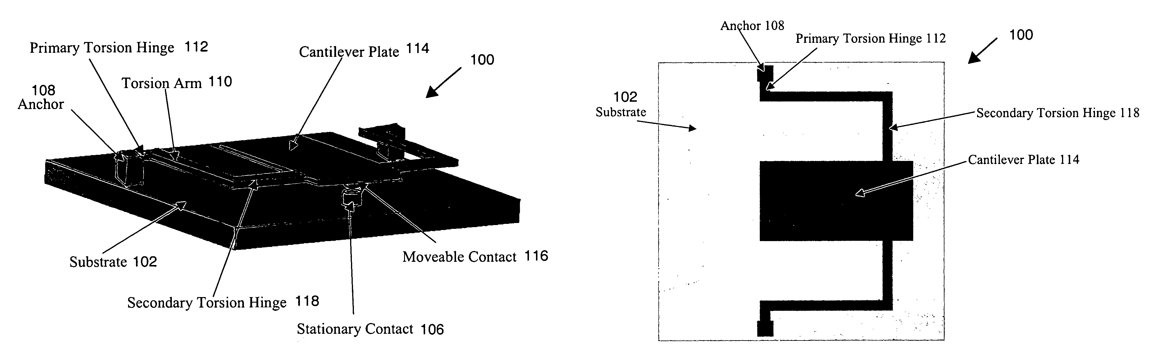
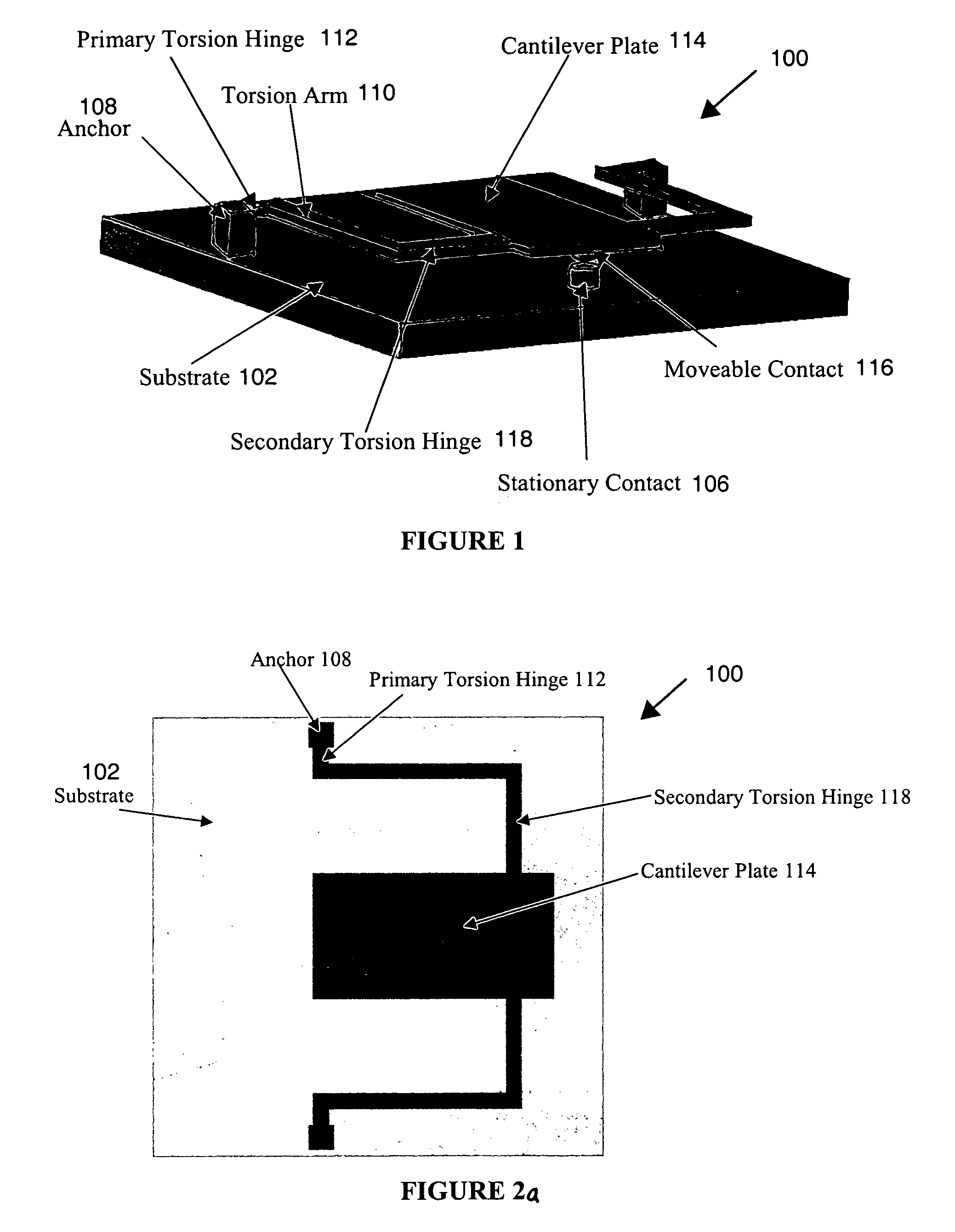
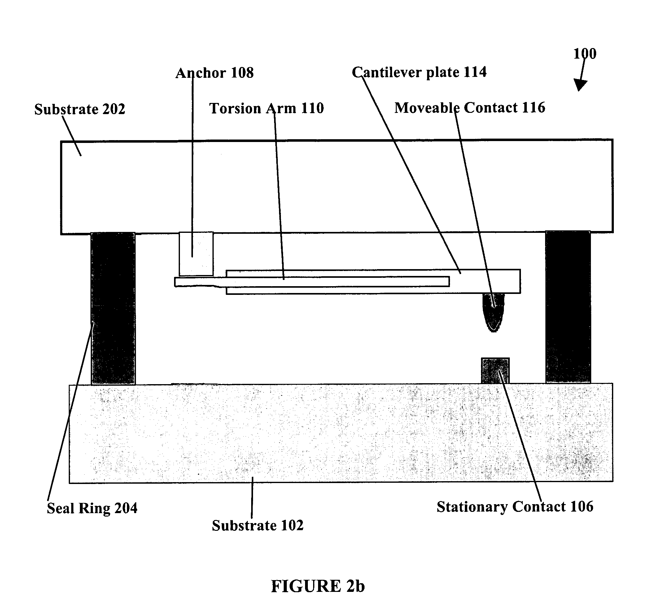
[0032]The two-stage cantilever design disclosed herein improves the reliability of MEMS with cantilever actuators by using a cantilever structure with a high actuation force, a scrubbing contact motion, and an unzipping motion for contact separation. In most single stage cantilevers, to have a reasonable gap for isolation purposes, most of the cantilever structure must be relatively distant from the substrate area with the applied voltage. With the two stage design, a substantial portion of the cantilever plate that is rotated about the second axis of the second torsion hinge can positioned to be extremely close to the substrate area with an applied voltage, thus providing a much higher electrostatic force while maintain a large gap. The higher pull-on forces associated with this invention provide better electrical contact in switches and relays. For devices such as MEMS switches, this translates into lower resistances and lower insertion losses, as well as greater power handling. I...


PUM


Abstract

Problems with the short lifetime of MEMS devices, low actuation forces, contaminant build-up on contacts, etc. are minimized by a MEMS device with an improved cantilever design that enables high force while maintaining large gaps. The improved cantilever design both allows for high force and fast switching while minimizing damage to contacts. The improved design can be fabricated on one or two substrates, which are bonded together with a seal ring to provide a packaged MEMS device.

Description

CROSS-REFERENCE TO RELATED APPLICATIONS[0001]This application claims the benefit of U.S. Provisional Application No. 60 / 679,817, filed on May 12, 2005, entitled “MEMS device,” the entire disclosure of which is hereby incorporated by reference herein in its entirety for all purposes.STATEMENT REGARDING FEDERALLY SPONSORED RESEARCH OR DEVELOPMENT[0002]This invention was made with Government support under Contract No. FA9453-04-C-0030 awarded by the U.S. Air Force, an AFRL Contract No. F33615-03-1-7002, and also under Subcontract 560500P412486 with Northeastern University. The Government has certain rights in the invention.BACKGROUND OF THE INVENTION[0003]1. Field of the Invention[0004]This invention pertains in general to MEMS device, and more specifically to an improved cantilever design for usage in a MEMS device[0005]2. Description of the Related Art[0006]Traditionally, many MEMS devices are actuated by simple, single-stage cantilevers, which are composed of a cantilever plate, a m...

Claims


Application Information

Patent Timeline
IPC IPC(8): H01H51/22
CPCH01H59/0009
Inventor COHN, MICHAEL B.
Owner MICROASSEMBLY TECH
Why Eureka
Try Eureka