Exposure apparatus

a technology of uv light and lithography, which is applied in the field of uv light, can solve the problems of limiting the critical dimension of lithography to a thinner thickness, and achieve the effect of maintaining the reflective index of the optical element as high and minimizing the maintenance frequency of the optical elemen

Inactive Publication Date: 2010-04-06
CANON KK
View PDF2 Cites 0 Cited by
  • Summary
  • Abstract
  • Description
  • Claims
  • Application Information

AI Technical Summary

Benefits of technology

[0007]The present invention is directed to an EUV exposure apparatus configured to maintain the reflective index of the optical element as high as possible and to minimize the maintenance frequency of the optical element by restraining attachments of released gas particles by degasifying to the optical element.

Problems solved by technology

However, the lithography using the UV light has limits in principle of exposing a thinner critical dimension (“CD”).

Method used


Image

  • Exposure apparatus
  • Exposure apparatus
  • Exposure apparatus

Examples


first embodiment

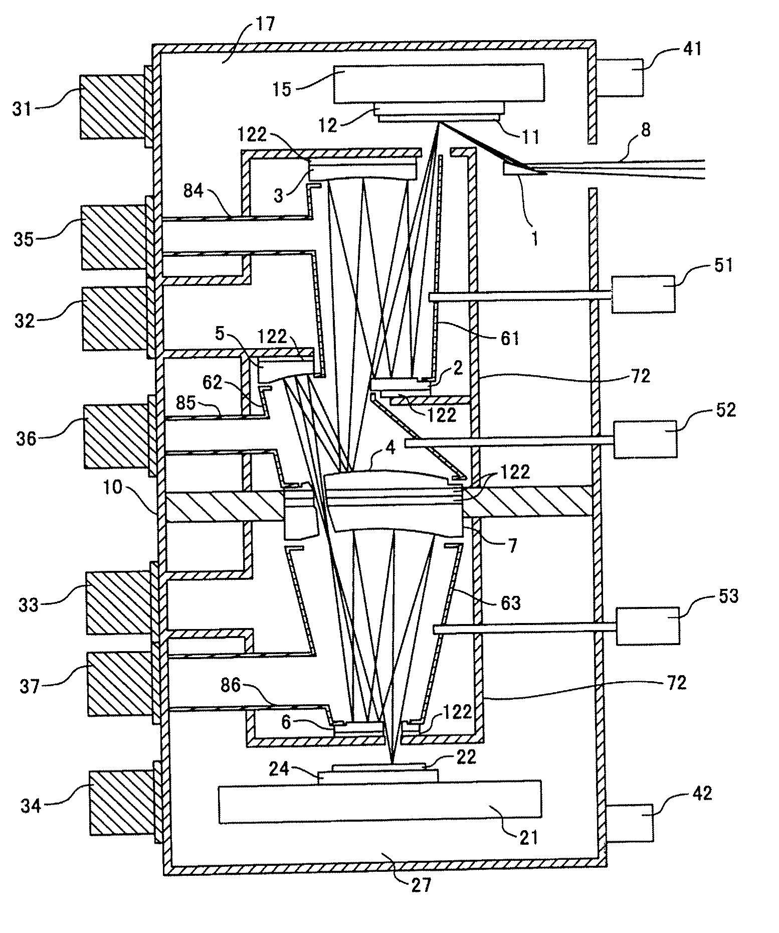
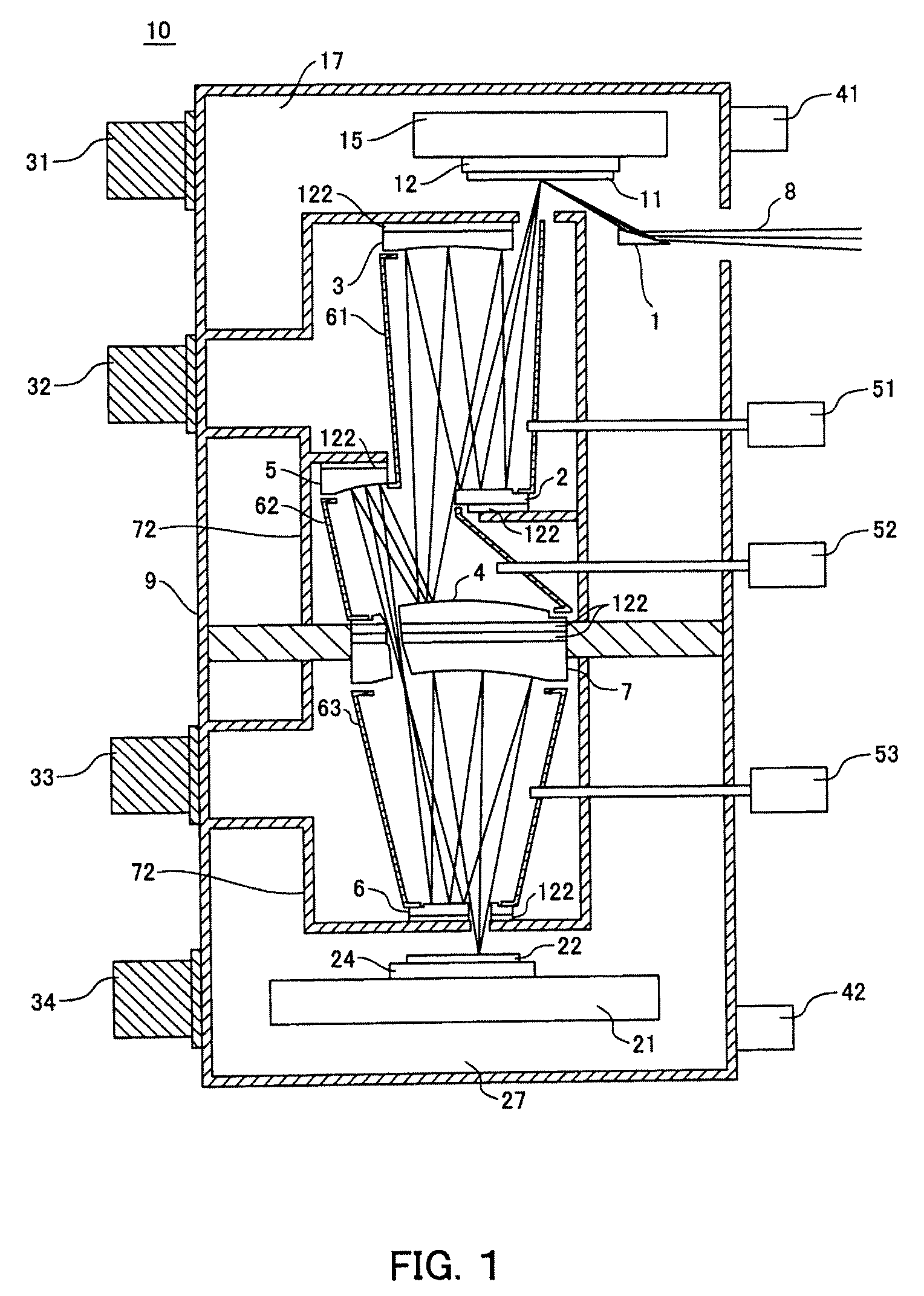
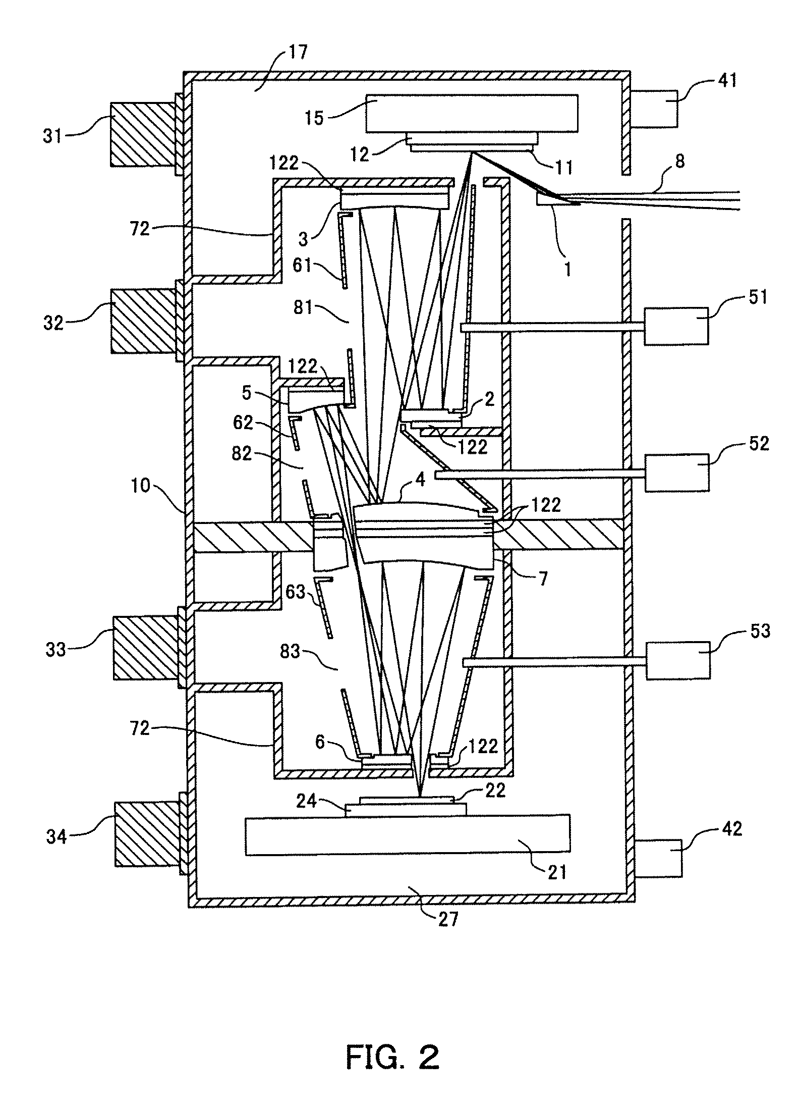
[0035]In order to reduce the degasifying density of the gas flowing into the partition wall due to the diffusion, it is effective to replace the atmospheres in the partition walls 61 to 63 with highly pure inert gas. The atmospheres in the partition walls 61 to 63 can be promptly replaced by promptly effusing the inert gas delivered to the inside of the partition walls 61 to 63 to the outside. While the first embodiment utilizes the aperture that allows a passage of the EUV light 8 as an aperture that allows escapes of the inert gas from the partition walls 61 to 63, this embodiment adds at least one aperture. The partition walls 61 to 63 are placed adjacent to the mirrors 2 to 7, and the apertures which the partition walls 61 to 63 can pass through are almost blocked by the mirrors 2 to 7. Therefore, a channel that connects the inside of each of the partition walls 61 to 63 to barrel 72 is narrow, and the inert gas is less likely to flow out of the partition walls 61 to 63. Apertur...

second embodiment

[0037]The partition walls 61 to 63 in the barrel 72 include exhausting ducts 84 to 86. The exhausting ducts 84 to 86 spatially connect internal spaces of the partition walls 61 to 63 to inlets of exhausting units 35 to 37, and evacuate the inert gas delivered into partition walls 61 to 63 from the exposure apparatus 10. This embodiment is effective where there are the driving part 122 and the sensor (not shown) adjacent to the apertures 81 to 83, through which the EUV light 8 does not pass, shown in the second embodiment, and the degasifying arises from there, and the released gas flows into the partition wall 61 to 63 due to the diffusion. The degasifying density in the partition walls 61 to 63 will be reduced when the atmospheres in the partition walls will be replaced with highly purified inert gases. An oscillation insulating part (not shown) is configured at connecting parts of the exhausting ducts 84 to 86 and the exhausting units 35 to 37 in order to reduce any influence on t...


PUM


Abstract

An EUV exposure apparatus is configured to maintain the reflective index of the optical element as high as possible and to minimize the maintenance frequency of the optical element by restraining attachments of released gas particles by degasifying to the optical element. An exposure apparatus is configured to expose a pattern of an original on a substrate by using extreme ultraviolet light. The exposure apparatus includes an optical element configured to receive the extreme ultraviolet light, a barrel configured to support the optical element, a chamber configured to store the barrel, and a partition wall configured outside and around an optical path of the extreme ultraviolet light in the barrel.

Description

BACKGROUND OF THE INVENTION[0001]1. Field of the Invention[0002]The present invention relates to an exposure apparatus that uses extreme ultraviolet (“EUV”) light for exposure.[0003]2. Description of the Related Art[0004]The semiconductor manufacturing photolithography has recently promoted use of the exposure light having a shorter wavelength from the i-line and the g-line to the KrF excimer laser and the ArF excimer laser. As the use of the exposure light having a shorter wavelength is promoted, a finer mask pattern can be transferred on to a wafer. However, the lithography using the UV light has limits in principle of exposing a thinner critical dimension (“CD”). Accordingly, the EUV lithography calls attentions, which uses the EUV light having a wavelength of 13 to 20 nm smaller than that of the UV light.[0005]The EUV light typically has a wavelength of 13.5 nm, and can provide a much smaller resolution than the conventional photolithography, but is likely to be absorbed into a ...

Claims


Application Information

Patent Timeline
Patent Type & Authority Patents(United States)
IPC IPC(8): G03B27/52
CPCG03F7/70883G03F7/70841
Inventor HAYASHI, TATSUYA
Owner CANON KK
Why Eureka
Try Eureka