Thermal storage unit and methods for using the same to heat a fluid

a technology of thermal storage unit and fluid, which is applied in the direction of heating type, separation process, immersion heating arrangement, etc., can solve the problem of prohibitively high cost, achieve the effect of reducing manufacturing cost, achieving desirable thermal mass or thermal storage properties, and substantial design flexibility

Active Publication Date: 2010-04-06
P10 IND INC
View PDF10 Cites 58 Cited by
  • Summary
  • Abstract
  • Description
  • Claims
  • Application Information

AI Technical Summary

Benefits of technology

[0018]These and other objects of the present invention are accomplished in accordance with the principles of the present invention by providing a TSU that is constructed using a casting process. A TSU according to the present invention may be constructed by first providing a conduit (or fluid conducting structure) and then subjecting that conduit to a casting process. The conduit may provide a pathway through which fluid flows through the TSU and the casting process may yield a cast that envelops the conduit with thermal storage material. The cast may have desirable thermal mass or thermal storage properties and may be fabricated from inexpensive material, such as ductile iron. The cast may permeate and occupy substantially all free space existing immediately adjacent to and near the conduit, resulting in a cohesive and integrated TSU in which the conduit and the cast may be fused together. Thus, after the cast sets, a solid thermal conducting mass having a fluid conducting passageway, as defined by the conduit, is provided.
[0019]An advantage of constructing a TSU using a casting process is that it provides substantial design flexibility, while reducing manufacturing cost. Design flexibility may be realized because the design and selection of the material composition of the conduit may be exercised independent of the design and selection of the material composition of the cast. This may enable TSUs according to the invention to have mass flow and thermal transfer properties and pressure containment not previously attainable in prior art TSUs. For example, the TSU may include a conduit that is a parallelepiped structure (e.g., a structure in which the fluid path passes back and forth along a particular axis a predetermined number of times), which is contained within a cast. It may not be possible to construct such a TSU using conventional machining techniques, and even if it were possible, the cost would be prohibitively expensive.
[0020]Moreover, the cast may permeate and occupy the free space existing between the parallelepiped structure, thereby maximizing the heat storage capacity and heat transfer capacity of the TSU. In addition to providing energy storage and efficient heat transfer, the cast may provide structural support for the TSU, thereby enabling it to contain pressurized fluids.
[0022]The TSU according to the invention may be used in a TACAS system. In a TACAS system, compressed gas may be sensibly heated by the TSU before it is routed to a turbine inlet of a turbine-generator. The heated compressed air drives a turbine, which powers an electrical generator to provide electrical power. An advantage of using the TSU according to the invention is that it may heat the compressed gas without requiring the use fuels, which when combusted cause pollution.

Problems solved by technology

It may not be possible to construct such a TSU using conventional machining techniques, and even if it were possible, the cost would be prohibitively expensive.

Method used


Image

  • Thermal storage unit and methods for using the same to heat a fluid
  • Thermal storage unit and methods for using the same to heat a fluid
  • Thermal storage unit and methods for using the same to heat a fluid

Examples


Embodiment Construction

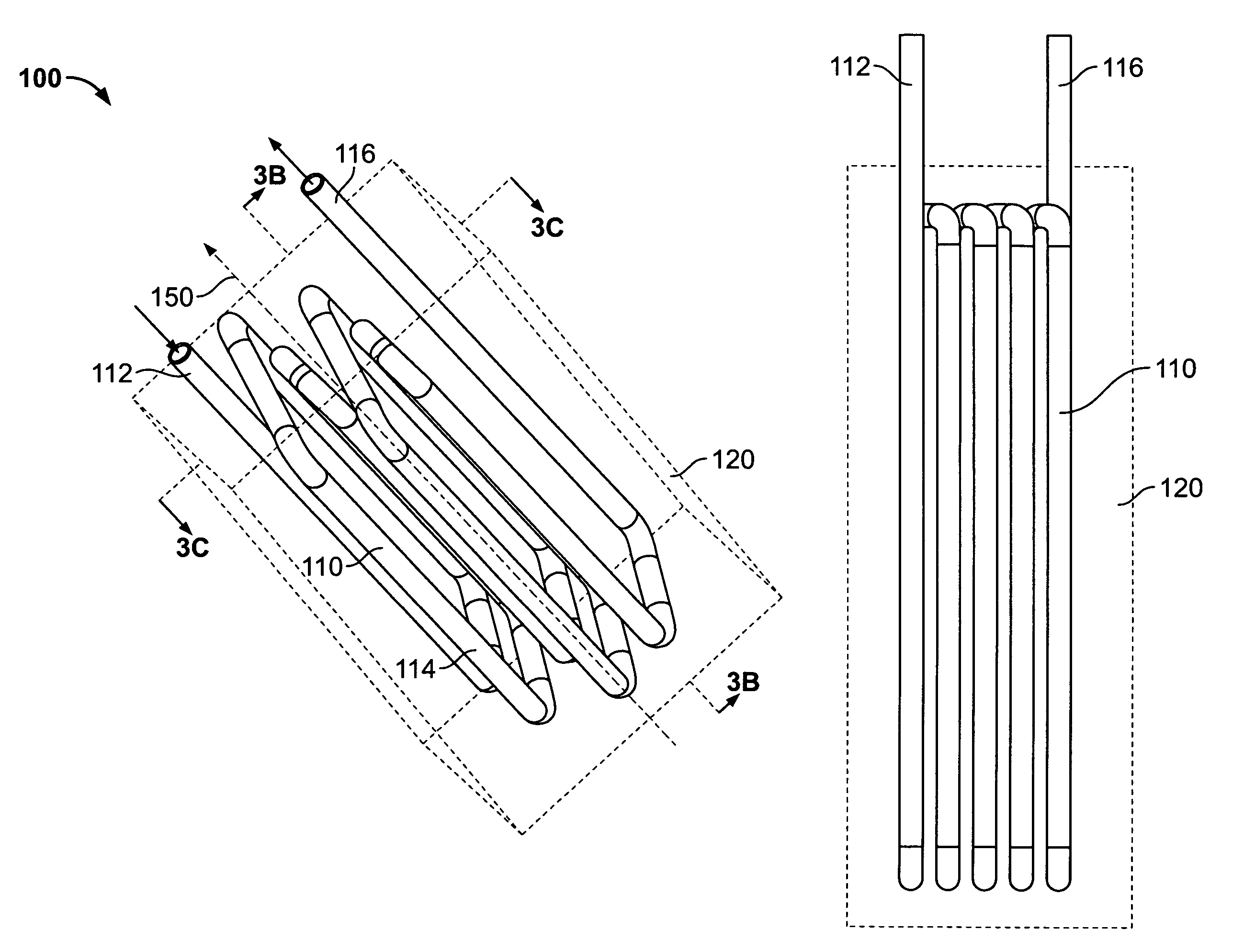
[0033]FIGS. 3A-C shows several views of a thermal storage unit (TSU) 100 that is in accordance with the principles of the present invention. In particular, FIG. 3A shows a three-dimensional view of thermal storage unit (TSU) 100 that is in accordance with the principles of the present invention. FIG. 3B shows a cross-sectional view of TSU 100 taken along the lines 3B-3B of FIG. 3A in accordance with the principles of the present invention. FIG. 3C shows a cross-sectional view of TSU 100 taken along the lines 3C-3C of FIG. 3A. It will be understood that any reference to FIG. 3 may include a reference to any one of FIGS. 3A-C.

[0034]TSU 100 may include conduit 110 and cast 120 and have longitudinal axis 150. As shown in FIG. 3, a significant portion of conduit 110 (e.g., conduit body 114) is enclosed by a dashed-line box, whereas inlet 112 and outlet 116 may remain unenclosed by the box. This box represents a cast 120 that envelops conduit 110 according to the invention. The manner or ...


PUM

PropertyMeasurementUnit
inner diameteraaaaaaaaaa
inlet temperatureaaaaaaaaaa
energyaaaaaaaaaa

Abstract

A thermal storage unit having at least one conduit around which a cast is made is provided. The thermal storage unit uses conventional piping or tubing to create conduits that economically maximize the surface area of flow in contact with the thermal mass by proving multiple passes for the fluid through the cast. This enables the thermal storage unit to economically provide heat storage as well as effective heat delivery and pressure containment for a fluid flowing through the conduit.

Description

BACKGROUND OF THE INVENTION[0001]This invention relates to thermal storage units (TSUs). More particularly, this invention relates to TSUs that provide sensible heat thermal energy storage and delivery in a way that increases efficiency and reduces costs compared to known TSUs.[0002]TSUs are well known and are often used in power delivery systems, such as compressed air storage (CAS) systems and thermal and compressed air storage (TACAS) systems. Such systems, often used to provide an available source of electrical power, often use compressed air to drive a turbine which powers an electrical generator.[0003]In TACAS systems, it is desirable to heat the compressed air prior to reaching the inlet port of the turbine. It is known that heated air, as opposed to ambient or cool air, enables the turbine to operate more efficiently. Therefore, a mechanism or system is needed to heat the air before providing it to the turbine. One approach is to use a suitable type of fuel-combustion system...

Claims


Application Information

Patent Timeline
Patent Type & Authority Patents(United States)
IPC IPC(8): F24H7/02F01K1/00
CPCF28D20/0056Y02E60/142Y02E10/20Y02E60/14Y10S165/539Y10S165/902
Inventor HUDSON, ROBERT S.PERKINS, DAVID E.HUDSON, DONALD M.BEATTY, DAVID J.STAMETS, DONALD L.PINKERTON, JOSEPH F.
Owner P10 IND INC
Why Eureka
Try Eureka