Focusing system and method for a charged particle imaging system

a technology of charged particles and imaging systems, applied in the field of focusing systems, can solve problems such as the distortion of the image of the detector, and achieve the effect of effective and efficient, reducing the aberration of the distortion image, and reducing the aberration

Active Publication Date: 2010-04-13
CARL ZEISS AG +1
View PDF19 Cites 25 Cited by
  • Summary
  • Abstract
  • Description
  • Claims
  • Application Information

AI Technical Summary

Benefits of technology

[0010]Typically the adjustment minimizes the aberration of the distorted image. In an embodiment of the present invention the aberration comprises an astigmatism from which the processor generates an error signal. The error signal has a magnitude proportional to the amount of defocusing, and a sign which enables the processor to determine if the image is “over-focused” or “under-focused.” The processor uses the error signal to adjust the generator and / or the surface position so that the distorted image does not display the astigmatism. Introducing an aberrating element into a charged beam system, and adjusting the aberration produced by the element to be a minimum, is an effective and efficient way of focusing a charged beam onto an irradiated surface. Furthermore, the focusing system does not require samples having contrast structures, can operate on bare unprocessed wafers, and does not introduce charging artifacts onto the irradiated surface.

Problems solved by technology

An aberrating element placed before the imaging detector, typically in the imaging path, causes the detector to produce a distorted image.

Method used


Image

  • Focusing system and method for a charged particle imaging system
  • Focusing system and method for a charged particle imaging system
  • Focusing system and method for a charged particle imaging system

Examples


Embodiment Construction

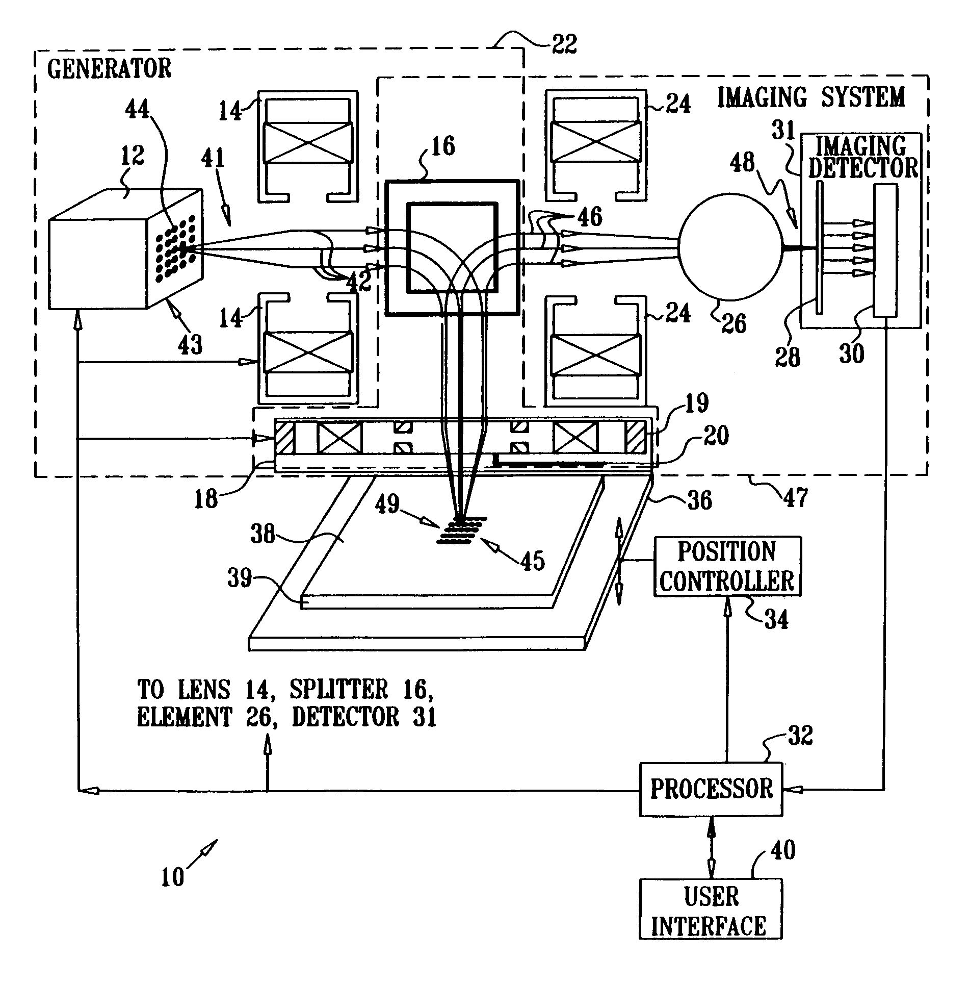
[0021]Reference is now made to FIG. 1, which is a schematic diagram of a charged particle beam focusing system 10, according to an embodiment of the present invention. System 10 includes a charged particle beam generator 22. By way of example, generator 22 is assumed to generate multiple charged beams 41 in parallel from a spot grid array (SGA) 44, and hereinbelow the multiple beams are assumed to comprise multiple electron beams, generated by a charged particle gun 12, which is herein assumed to be a multiple electron beam gun. By way of example, except where otherwise stated it is assumed that array 44 is a generally rectangular array aligned with horizontal and vertical axes. It will be appreciated, however, that the scope of the present invention is not limited to a particular type or alignment of SGA 44, and includes substantially all types and alignments of such arrays.

[0022]It will also be appreciated that the scope of the present invention is not limited to focusing a partic...


PUM


Abstract

Apparatus for focusing a charged particle beam onto a surface, including a charged particle beam generator which is adapted to project the charged particle beam onto a location on the surface, thereby causing charges to be emitted from the location. The apparatus further includes an imaging detector which is adapted to receive the charges so as to form an image of the location, and an aberrating element which is positioned before the imaging detector and which is adapted to produce an aberration in the image. A processor is adapted to receive the image and to adjust at least one of the charged particle beam generator and a position of the surface in response to the aberration.

Description

CROSS-REFERENCE TO RELATED APPLICATION[0001]The present patent application is a continuation of International Application No. PCT / US2005 / 001756 filed Jan. 20, 2005, which claims priority from Provisional Application No. 60 / 540,719 filed Jan. 29, 2004.FIELD OF THE INVENTION[0002]The present invention relates generally to focusing systems, and specifically to focusing charged particle beams.BACKGROUND OF THE INVENTION[0003]Charged particle beams, such as those that are used in focused ion beam or scanning electron microscopes, are typically focused by scanning the beam over a sample with sharp edges. The incident charged beam generates a scanned image of the sample, and the beam is focused by maximizing the contrast of the scanned image. However, this focusing system requires a patterned sample with sharp features.[0004]The same method of scanning and maximizing contrast in the scanned image may also be used in wide area particle beam systems used for electron beam inspection and lith...

Claims


Application Information

Patent Timeline
Patent Type & Authority Patents(United States)
IPC IPC(8): G21K1/08H01J3/14H01J37/153H01J37/21H01J37/22H01J37/28H01J37/29
CPCH01J37/153H01J37/21H01J37/222H01J37/265H01J37/28H01J37/29H01J2237/31774H01J2237/1532H01J2237/216H01J2237/2538H01J2237/2817
Inventor ROGERS, STEVEN ROBERT
Owner CARL ZEISS AG
Why Eureka
Try Eureka