Method of and apparatus for reducing noise

a technology of noise reduction and noise reduction, applied in the field of noise reduction methods and apparatuses, can solve the problems of user inability to suppress all vibrations, ineffective structures, and inability to so as to reduce noise, reduce circuit scale and cost, and be convenient to carry out

Inactive Publication Date: 2010-04-13
SONY CORP
View PDF19 Cites 20 Cited by
  • Summary
  • Abstract
  • Description
  • Claims
  • Application Information

AI Technical Summary

Benefits of technology

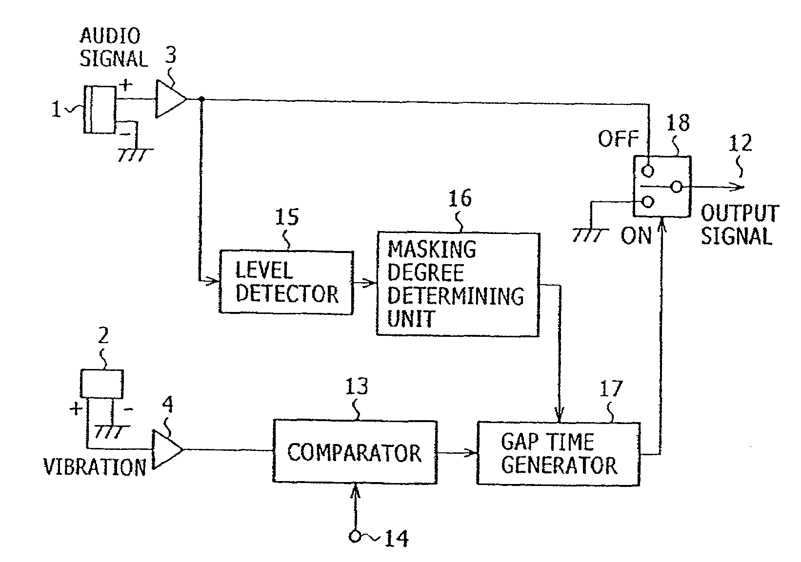
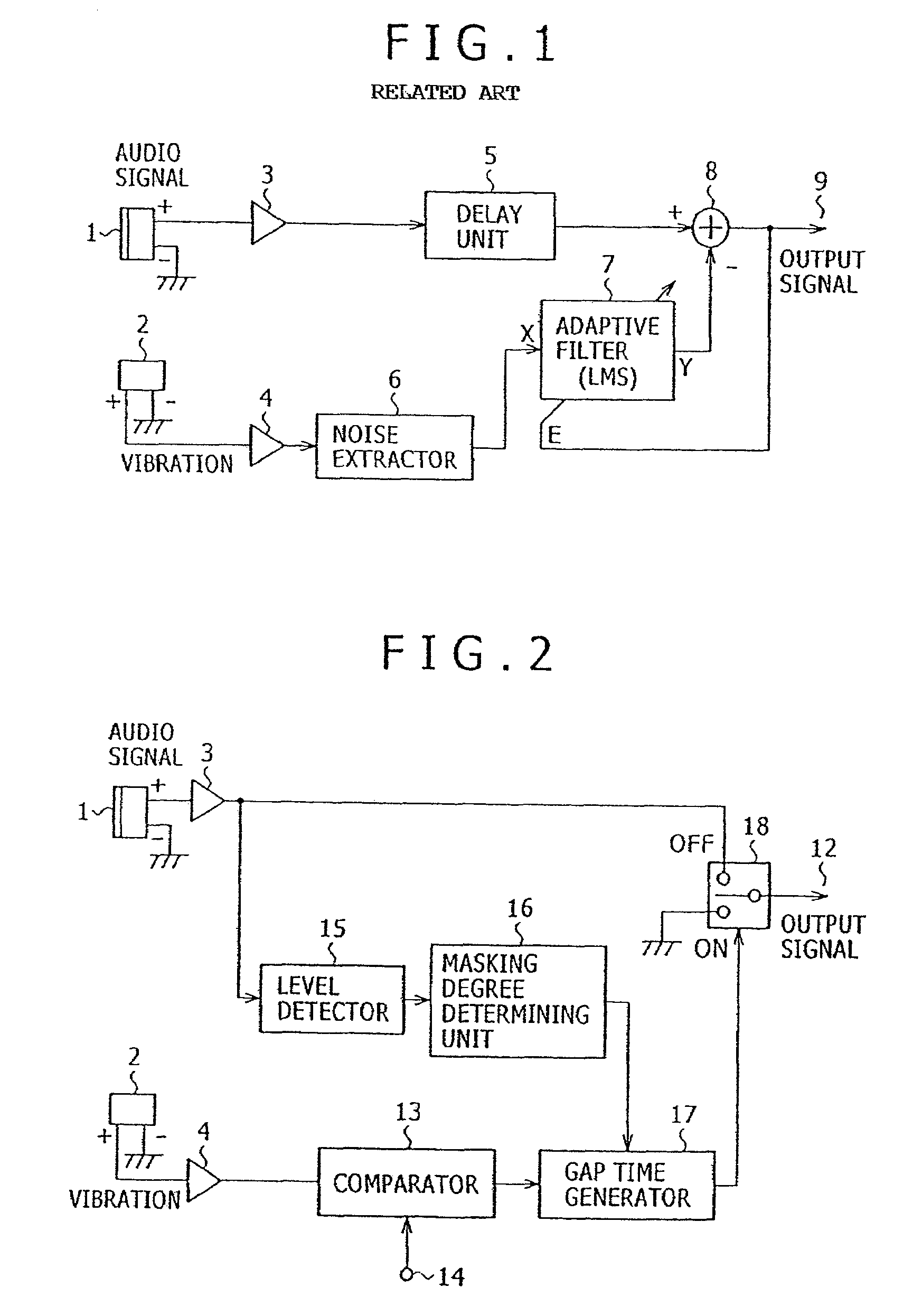
[0022]According to the present invention, there is also provided a method of reducing noise in an input audio signal, including the steps of generating a noise timing signal corresponding to a noise producing period of noise introduced from a noise source and contained in at least one audio signal, removing the noise from the audio signal, selectively outputting the audio signal and a signal from the noise removing step, detecting a signal level of the audio signal, and determining from the signal level detected by the signal level detecting step a gap period for which the audio signal is masked by the human auditory system. The selectively outputting step outputs the signal from the noise removing step in a period corresponding to the gap period within the noise producing period of the noise timing signal, and outputs the audio signal in other than the gap period.
[0023]With the above arrangement, when instantaneous noise, e.g., shock noise or seek noise, produced in a recording mode of a digital consumer electronics device incorporating a small-size microphone is gated off from an audio signal from the microphone, a gap time in which to gate off the instantaneous noise is controlled so that no reproducing failure occurs even if the audio signal is also simultaneously gated off, based on the human auditory masking effect. As noise is simply gated off only during a noise producing period according to the human auditory masking effect, unlike a noise reduction process using an adaptive filter as disclosed in prior applications Nos. 2002-367234 and 2003-285294, the noise reduction process according to the present invention requires a reduced circuit scale and cost, and can easily be carried out.
[0025]According to the present invention, there is further a method of reducing noise in an input audio signal, including the steps of dividing at least one audio signal into a plurality of audio signals in respective bands, generating a noise timing signal corresponding to a noise producing period of noise introduced from a noise source and contained in the audio signals from the dividing step, removing the noise from the audio signals, selectively outputting the audio signal and signals from the noise removing step, detecting signal levels of the audio signals, and determining, from the signal levels detected by the level detecting step, gap periods for which the audio signals are masked by the human auditory system. The selectively outputting step outputs the signals from the noise removing step in periods corresponding to the gap periods within the noise producing period of the noise timing signal, and outputs the audio signal in other than the gap periods, adds the audio signals in the respective bands into a sum signal, and outputs the sum signal.
[0026]With the above arrangement, since the audio signal is divided into a plurality signals in respective bands, gap periods for masking the audio signals are determined in the respective bands, the noise is removed, and the audio signals in the respective bands are combined together, masking degrees can be determined and optimized in the respective bands for noise reduction. For a divided band that can easily be masked, the gap period can further be increased to advantage. For a divided band free of noise, no noise needs to be gated off, resulting in higher efficiency.
[0028]According to the present invention, there is also provided a method of reducing noise in an input audio signal, including the steps of outputting a differential component between a plurality of audio signals from a plurality of microphones, extracting noise introduced from a noise source and contained in an output signal from the processing step, generating a noise timing signal corresponding to a noise producing period of the noise, removing the noise from the audio signals, selectively outputting the audio signal and a signal from the noise removing step, detecting a signal level of the audio signal, and determining from the signal level detected by the level detector a gap period for which the audio signals are masked by the human auditory system. The selectively outputting step outputs the signal from the noise removing step in a period corresponding to the gap period within the noise producing period of the noise timing signal, and outputs the audio signals in other than the gap period.

Problems solved by technology

Because of the small size of those digital consumer electronics apparatus, the user tends to inadvertently touch the microphone or noise is likely to propagate through the cabinet to the microphone when various functional switches are clicked during a recording mode.
Therefore, when in a reproducing mode, undesirable touch noise or click noise may possibly be reproduced from the apparatus.
Furthermore, since the microphone is positioned closely to a recording device such as a tape device or a disk device housed in the cabinet, vibration noise or sound noise produced by the recording device is highly likely input to the microphone.
However, these structures are not effective enough to suppress all the vibrations.
When strong vibrations are applied or depending on the vibration frequency, the insulator is ineffective or may resonate at an inherent frequency.
These proposed structures are difficult to design, and the design difficulty is responsible for obstacles to efforts to reduce the cost and size.
The noise that is picked up by the microphone unit is caused by not only vibrations transmitted through the cabinet, but also sounds propagated through the air.
Since the noise is transmitted through complex paths to the microphone unit, the conventional passive noise reduction techniques are subject to limitations and have not reached a level that the user satisfies.
A time delay caused by the processing operations that are required cannot be ignored, resulting in a need for simultaneously delaying the audio signal.
Accordingly, desired sounds cannot be recorded in real time.

Method used


Image

  • Method of and apparatus for reducing noise
  • Method of and apparatus for reducing noise
  • Method of and apparatus for reducing noise

Examples


Embodiment Construction

[0047]Digital consumer electronics apparatus incorporating a small-size microphone in their cabinet, e.g., video cameras, digital cameras, etc. are becoming smaller and smaller in size in recent years. Therefore, the recording / reproducing device, which includes a tape device or a disk device, in such an apparatus is positioned closely to the microphone, and tends to apply mechanical shock noise produced thereby easily to the microphone. Because of the small size of digital consumer electronics apparatus, when the user operates a zooming or focusing controller or any of various functional switches while in a camera exposure mode, it is often for the user to inadvertently touch a cabinet area near the microphone, causing noise to propagate through the cabinet to the microphone. Therefore, when in a reproducing mode, undesirable touch noise or click noise is possibly reproduced from the apparatus. While in the case the apparatus operates in the camera exposure mode in a relatively quie...


PUM


Abstract

An apparatus for reducing noise includes a comparator for generating a noise timing signal corresponding to a noise producing period of noise introduced from a noise source and contained in an audio signal, a gap time generator for generating a gap period in which to remove noise from the audio signal, a selector switch for selectively outputting the audio signal and a noise-removed signal, a level detector for detecting a signal level of the audio signal, and a masking degree determining unit for determining from the signal level detected by the level detector a gap period for which the audio signal is masked by the human auditory system. The selector switch outputs the noise-removed signal in a period corresponding to the gap period within the noise producing period of the noise timing signal, and outputs the audio signal in other than the gap period.

Description

BACKGROUND OF THE INVENTION[0001]The present invention relates to a method of and an apparatus for reducing noise when recording an audio signal by a small-size microphone that is incorporated in a digital consumer electronics device.[0002]Growing efforts have in recent years been made to reduce the size of digital consumer electronics apparatus incorporating a small-size microphone in their cabinet, e.g., video cameras, digital cameras, IC recorders, etc. Because of the small size of those digital consumer electronics apparatus, the user tends to inadvertently touch the microphone or noise is likely to propagate through the cabinet to the microphone when various functional switches are clicked during a recording mode. Therefore, when in a reproducing mode, undesirable touch noise or click noise may possibly be reproduced from the apparatus. Furthermore, since the microphone is positioned closely to a recording device such as a tape device or a disk device housed in the cabinet, vib...

Claims


Application Information

Patent Timeline
Patent Type & Authority Patents(United States)
IPC IPC(8): G10L21/02H04R3/00
CPCG10L21/0208B22C9/123B22C9/10
Inventor OZAWA, KAZUHIKO
Owner SONY CORP
Why Eureka
Try Eureka