Fluid dynamic bearing having pressure-generating surface patterns

a dynamic bearing and pressure-generating surface technology, applied in the direction of bearings, shafts and bearings, rotary bearings, etc., can solve the problems of reducing deviations from the ideal form, and affecting the energy dissipation of the bearing, so as to improve the shape of the pressure-generating surface patterns and reduce the negative effect of manufacturing tolerances on the pumping action of the patterns

Inactive Publication Date: 2010-04-20
MINEBEA CO LTD
View PDF12 Cites 11 Cited by
  • Summary
  • Abstract
  • Description
  • Claims
  • Application Information

AI Technical Summary

Benefits of technology

[0008]It is thus the object of the invention to improve the shape of the pressure-generating surface patterns in a fluid dynamic bearing system such that the negative effects on the pumping action of the patterns caused by manufacturing tolerances are reduced.

Problems solved by technology

In actual bearings, however, deviations from this ideal form occur.
To prevent this happening, it may be necessary to give the surface patterns a highly pronounced asymmetry to ensure a defined pumping direction, which, however, has a negative impact on the energy dissipation of the bearing.

Method used


Image

  • Fluid dynamic bearing having pressure-generating surface patterns
  • Fluid dynamic bearing having pressure-generating surface patterns
  • Fluid dynamic bearing having pressure-generating surface patterns

Examples


Embodiment Construction

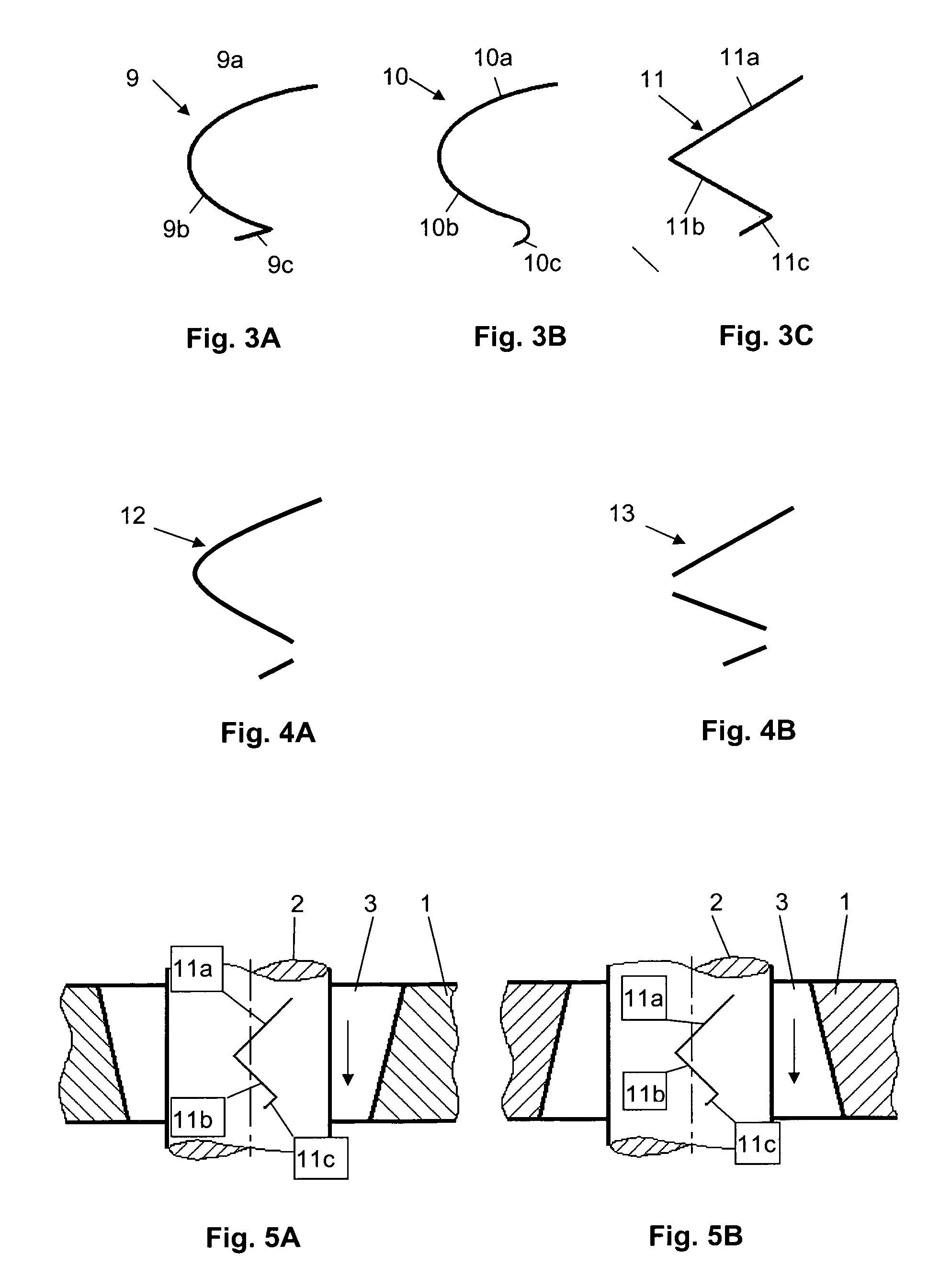
[0025]Examples of patterns according to the invention are illustrated in FIGS. 3 to 6. When the geometry of the patterns is split, the influence of conical bearing partners can be compensated in part.

[0026]In the following, the directions are indicated by the terms left, right, upward and downward. These direction references apply to the drawings being viewed vertically.

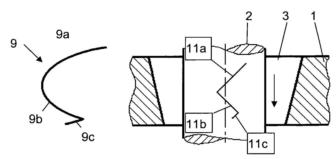
[0027]FIG. 3A shows an asymmetric pattern 9, having two curved, parabolic sections 9a, 9b connected to one another and a straight section 9c affixed at an acute angle. If this pattern were to be formed on a shaft 2, for example, (see FIG. 1) and the shaft rotated towards the right, sections 9a and 9c each generate a downward pumping action, whereas section 9b generates an upward pumping action. In the case of a uniform bearing gap, the downward pumping action thus predominates since section 9b is shorter than sections 9a and 9c together.

[0028]FIG. 3B shows an asymmetric pattern 10 having two curved, parabolic section...


PUM


Abstract

A fluid dynamic bearing system having pressure-generating asymmetric surface patterns, having at least two bearing parts that are rotatable with respect to each other and form a bearing gap filled with a bearing fluid between associated bearing surfaces. The surface patterns are disposed on at least one bearing surface so that hydrodynamic pressure is generated within the bearing gap when the bearing parts rotate with respect to each other. Each surface pattern comprises at least three sections, each section generating a pumping action in a defined direction, and the pumping actions of adjacent sections being substantially aligned in opposite directions. Due to the special geometry of the surface patterns, tolerances in the geometry of the bearing gap have a less significant effect on the pre-defined pumping direction.

Description

BACKGROUND OF THE INVENTION[0001]The invention relates to a fluid dynamic bearing, particularly a radial bearing, having pressure-generating surface patterns according to the characteristics outlined in the preamble of claim 1.PRIOR ART[0002]Fluid dynamic bearings generally comprise at least two bearing parts that are rotatable with respect to each other and form a bearing gap filled with a bearing fluid, e.g. air or bearing oil, between the associated bearing surfaces. Surface patterns that are associated with the bearing surfaces and that act on the bearing fluid are provided using a well-know method. In fluid dynamic bearings, the surface patterns taking the form of depressions or raised areas are usually formed on one or both bearing surfaces. These patterns formed on the appropriate bearing surfaces of the bearing partners act as bearing and / or pumping patterns that generate hydrodynamic pressure within the bearing gap when the bearing parts rotate with respect to each other. I...

Claims


Application Information

Patent Timeline
Patent Type & Authority Patents(United States)
IPC IPC(8): F16C17/00
CPCF16C33/107F16C17/02
Inventor ENGESSER, MARTINSCHWAMBERGER, STEFAN
Owner MINEBEA CO LTD
Why Eureka
Try Eureka