Method and apparatus for molding a laminated trim component without use of slip frame

a technology of laminated trim and slip frame, which is applied in the direction of shaping conveyors, baking, domestic objects, etc., can solve the problems of reducing affecting the quality of molding products, so as to reduce the size and space requirement of molding apparatus or systems, and reduce the amount of material waste

Active Publication Date: 2010-04-20
HERBERT OLBRICH
View PDF23 Cites 14 Cited by
  • Summary
  • Abstract
  • Description
  • Claims
  • Application Information

AI Technical Summary

Benefits of technology

[0010]In view of the above, it is an object of the present invention to provide a method and an apparatus for molding a sheet-form material to produce a molded product, while avoiding the use of a separate or external slip frame. It is a further particular object of the invention to minimize the amount of material waste at an edge or edges of the molded product. Another object of the invention is to reduce the size and space requirement of a molding apparatus or system. The invention further aims to avoid or overcome the disadvantages of the prior art, and to achieve additional advantages, as apparent from the present specification. The attainment of these objects is, however, not a required limitation of the claimed invention.
[0012]The above objects have further been achieved according to the invention in a method of molding a sheet-form raw material blank to form a molded product. The method can be carried out using an apparatus according to the invention. The method involves providing a sheet-form raw material blank between the first and second mold tools, then moving and clamping the first and second outer edge molds together so as to clampingly hold an edge rim of the raw material blank, thereafter moving and closing the first and second inner core molds together so as to carry out the three-dimensional molding deformation of the raw material blank, while allowing at least some slipping of the edge rim of the raw material blank between the first and second outer edge molds inwardly toward the mold cavity formed between the first and second inner core molds. Finally, the first and second mold tools are opened relative to each other, and the molded product may be removed from the mold cavity.

Problems solved by technology

The conventionally known apparatuses as described above suffer several disadvantages arising directly due to the use of the slip frame.
Most importantly, the use of a slip frame necessarily requires the provision of a rather large surplus edge rim of the raw material protruding laterally beyond the edge of the mold.
However, the edge rim waste becomes gravely significant in connection with relatively small products or products that are relatively narrow but long.
This is conventionally unavoidable because the conventional slip frame is spaced laterally by at least about 10 mm away from the outer edges of the mold, the slip frame itself typically has a width of at least about 25 mm, and a surplus rim edge protruding at least about 15 mm outwardly from the slip frame is typically left to allow for the slippage during molding as well as to allow a clamp frame or needle frame of a material transport mechanism to grasp the edges of the material.
This can result in about 20% material waste when molding a typical motor vehicle door panel, for example.
A further disadvantage of using a conventional slip frame is that the overall apparatus then takes up a lot of space, i.e. is very large due to the extra space required by the slip frames at the sides of the mold tools.
The conventional arrangements thus often take up an unacceptably large space, regardless whether relatively small-area products or relatively large-area products are being produced.
As a result, the overall molding system takes up a disproportionately large space and is especially very long in comparison to the length of the product being produced.

Method used


Image

  • Method and apparatus for molding a laminated trim component without use of slip frame
  • Method and apparatus for molding a laminated trim component without use of slip frame
  • Method and apparatus for molding a laminated trim component without use of slip frame

Examples


Embodiment Construction

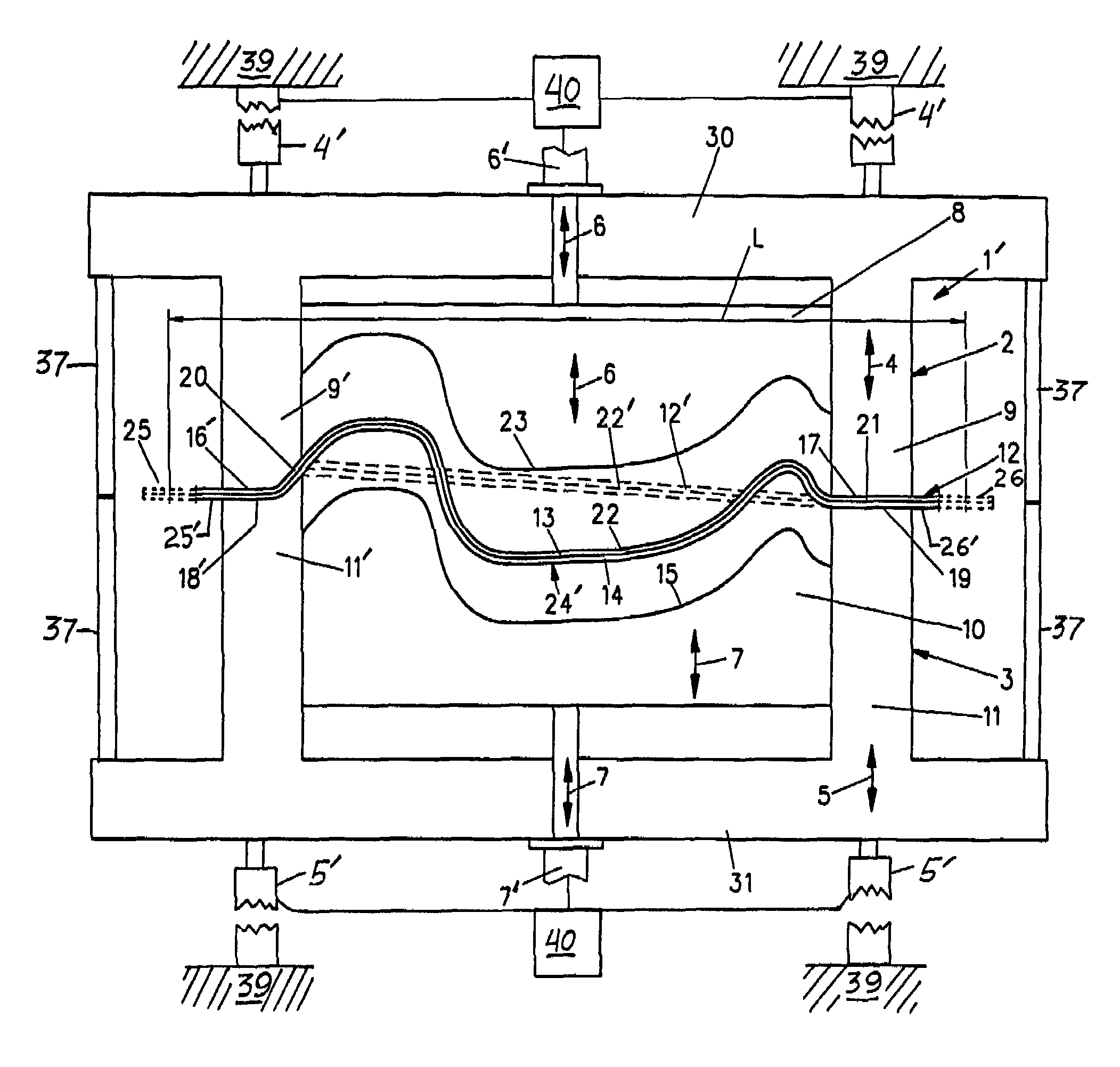
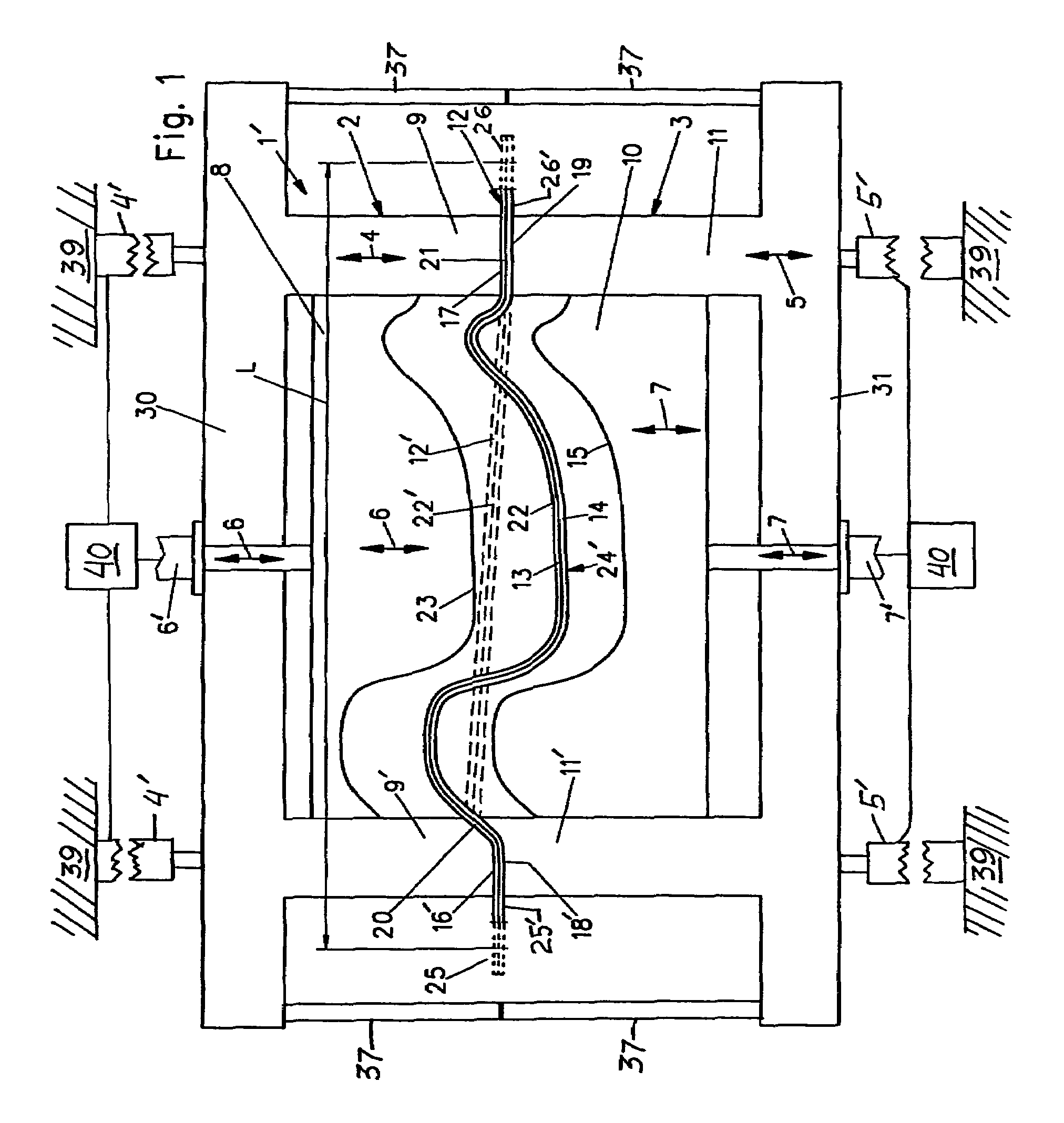
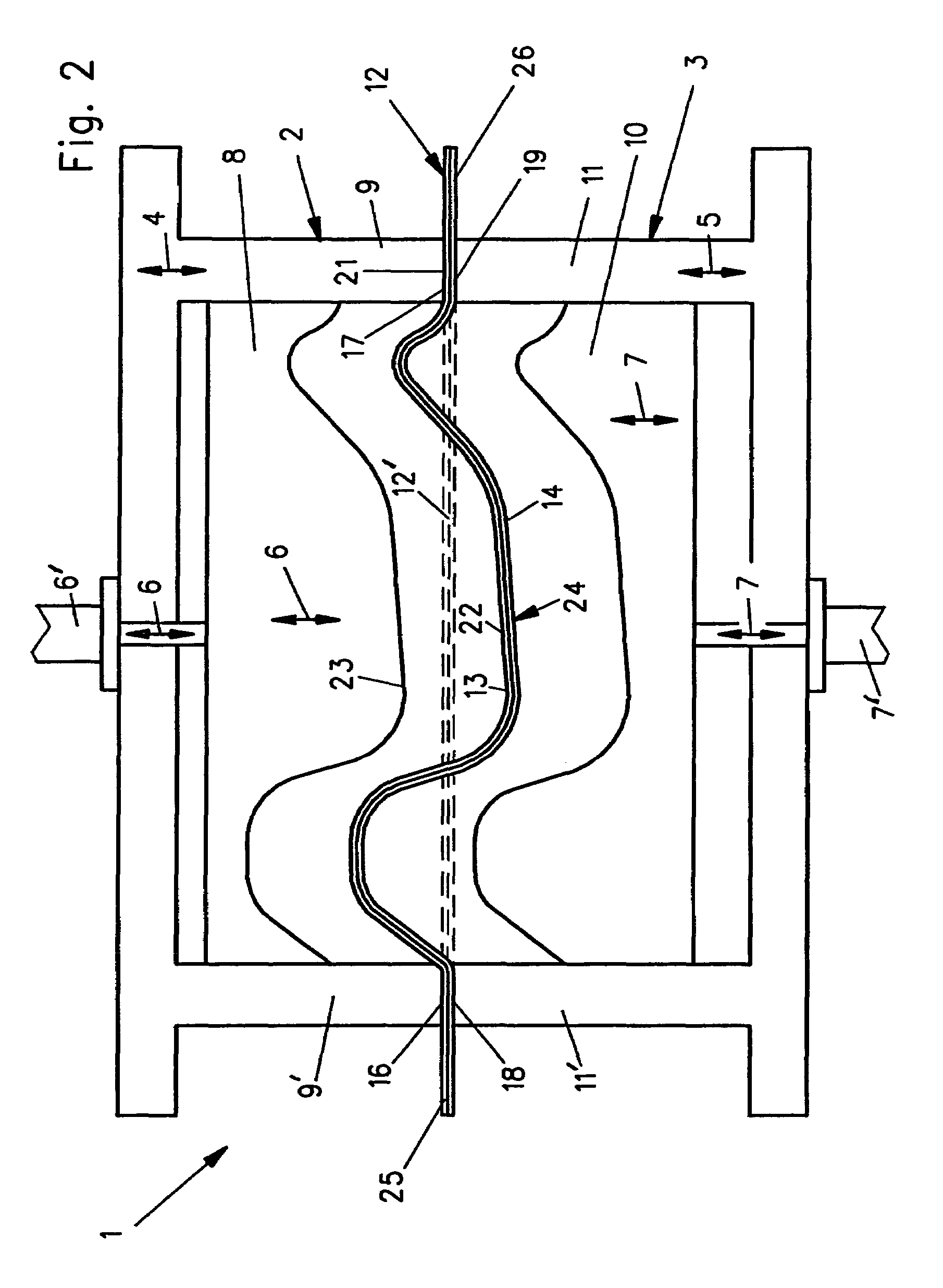
[0023]FIGS. 1 and 2 are basically similar schematic diagrams of two slightly different variants of a molding apparatus 1, 1′ according to the invention. First the similar or consistent features of the apparatuses 1 and 1′ will be described, and then the difference will be described.

[0024]The apparatus 1, 1′ comprises a structural machine frame 39 supporting an upper or first mold tool 2, and a lower or second mold tool 3, which are movable relative to one another and relative to the machine frame 39. More particularly, the upper or first mold tool 2 includes a main mold or inner core mold 8 and at least one outer frame or outer edge mold 9, 9′ arranged at at least one lateral edge or a perimeter of the inner core mold 8. Similarly, the lower or second mold tool 3 includes an inner core mold 10 and at least one outer edge mold 11, 11′ arranged at at least one lateral edge or a perimeter of the inner core mold 10. The outer edge mold or molds 9, 9′ can extend continuously around the p...


PUM

PropertyMeasurementUnit
gap spacing sizeaaaaaaaaaa
temperaturesaaaaaaaaaa
widthaaaaaaaaaa

Abstract

An apparatus for producing a molded product from a sheet-form raw material blank has first and second mold tools that each respectively include a respective inner core mold and a respective outer edge mold laterally adjacent thereto. Drive elements drive the outer edge molds relative to a machine frame, and drive the inner core molds relative to the outer edge molds. A molding process involves closing the outer edge molds to hold an edge rim of the material blank while allowing slippage thereof, and then closing the inner core molds to three-dimensionally deform and mold a central portion of the material blank while pulling required additional material by slippage through the outer edge molds. A separate slip frame is not used. The edge rim held by the outer edge molds remains as a permanent mounting rim or flange of the finished molded product. Edge waste is minimized.

Description

PRIORITY CLAIM[0001]This application is based on and claims the priority under 35 U.S.C. §119 of German Patent Application 10 2004 034 792.1, filed on Jul. 19, 2004, and European Patent Application 0 50 04 510.3, filed Mar. 2, 2005, the entire disclosures of both of which are incorporated herein by reference.FIELD OF THE INVENTION[0002]The invention relates to a method and an apparatus for molding products, such as interior trim components for motor vehicles, from multi-layered sandwich laminate raw material blanks.BACKGROUND INFORMATION[0003]It is well known to produce laminated molded products, such as interior trim components for motor vehicles, from raw material blanks or webs or mats of multi-layered raw material, for example including thermoplastic fibers that serve as a thermoplastic meltable adhesive and matrix, as well as other fibers serving as a reinforcement or filler. A great variety of different methods and apparatuses for molding such a multi-layered raw material to p...

Claims


Application Information

Patent Timeline
Patent Type & Authority Patents(United States)
IPC IPC(8): B29C51/20
CPCB29C43/36B29C33/20B29L2031/3041B29K2105/0854B29C2043/3602
Inventor SPENGLER, GERHARD
Owner HERBERT OLBRICH
Why Eureka
Try Eureka