Profiling float and usage of the profiling float

a profiling float and profiling technology, applied in special-purpose vessels, underwater equipment, instruments, etc., can solve the problems of difficult to difficult to minutely control the flow rate of fluid, and difficult to strictly control the degree of valve opening, etc., to achieve the effect of minutely and surely controlling the effective buoyancy acting

Inactive Publication Date: 2010-04-20
NAT INST FOR MATERIALS SCI
View PDF14 Cites 3 Cited by
  • Summary
  • Abstract
  • Description
  • Claims
  • Application Information

AI Technical Summary

Benefits of technology

[0031]According to the profiling float of the present invention, both of amounts of the fluid for control of buoyancy discharged from and supplied to the bladder are actively controlled by the gear pump that is a reversible type pump, whereby the amounts of the fluid for control of buoyancy supplied to and discharged from the bladder can be accurately controlled. As a result, the volume of the fluid for control of buoyancy existing within the bladder is surely controlled. Accordingly, the volume of the bladder is minutely controlled, and consequently the effective buoyancy of the profiling float is controlled with high accuracy.
[0032]The gear pump is used in combination with the fluid for control of buoyancy having a relatively high viscosity as described above, whereby a braking function is basically exhibited, so that an unintended operation is surely prevented even under such environment as a high pressure is applied to the fluid for control of buoyancy, and the rotational angle and rotational speed of the gear are accurately controlled. Accordingly, the amount of the fluid transferred is always controlled with high accuracy. As a result, the volume of the bladder is always minutely controlled, and after all the buoyancy of the profiling float is controlled with high accuracy.
[0033]Since the gear pump is of a small size and lightweight compared with the conventional one-way transfer type pump, the miniaturization and weight saving of the whole profiling float can be realized. As a result, the high efficiency of the electric power consumed by the profiling float can be achieved, and so a long service life is realized, and moreover a high degree of freedom is achieved in design conditions such as the form of the float chamber.

Problems solved by technology

However, the valve mechanism 525 is difficult from the mechanism thereof to strictly control the degree of opening of the valve under pressure.
After all, it is difficult to minutely control the flow rate of the fluid for control of buoyancy discharged from the bladder 522, so that it is difficult to minutely control the amount of the fluid for control of buoyancy within the bladder 522.
Accordingly, the profiling float involves a problem that the predetermined effective buoyancy value can be realized with high accuracy, and after all, it is actually very difficult to realize the predetermined moving speed of the profiling float 50 and the operation in the sea such as the staying in the vertical direction at the predetermined depth with high accuracy.
In addition, the float involves a problem that since the pressure applied to the valve mechanism 525 is considerably high when the profiling float 50 is located at a deep depth in particular, the above-described problem becomes more marked.
In addition, the valve mechanism 525 involves a problem that the amount of the fluid for control of buoyancy passing through the valve mechanism 525 varies according to, for example, the pressure applied to the fluid for control of buoyancy even when the degree of opening of the valve is kept constant, so that the amount is not fixedly stabilized, and after all, it is difficult to accurately control the flow rate of the fluid for control of buoyancy.

Method used


Image

  • Profiling float and usage of the profiling float
  • Profiling float and usage of the profiling float
  • Profiling float and usage of the profiling float

Examples


Embodiment Construction

[0085]The profiling float according to the present invention will hereinafter be described in detail.

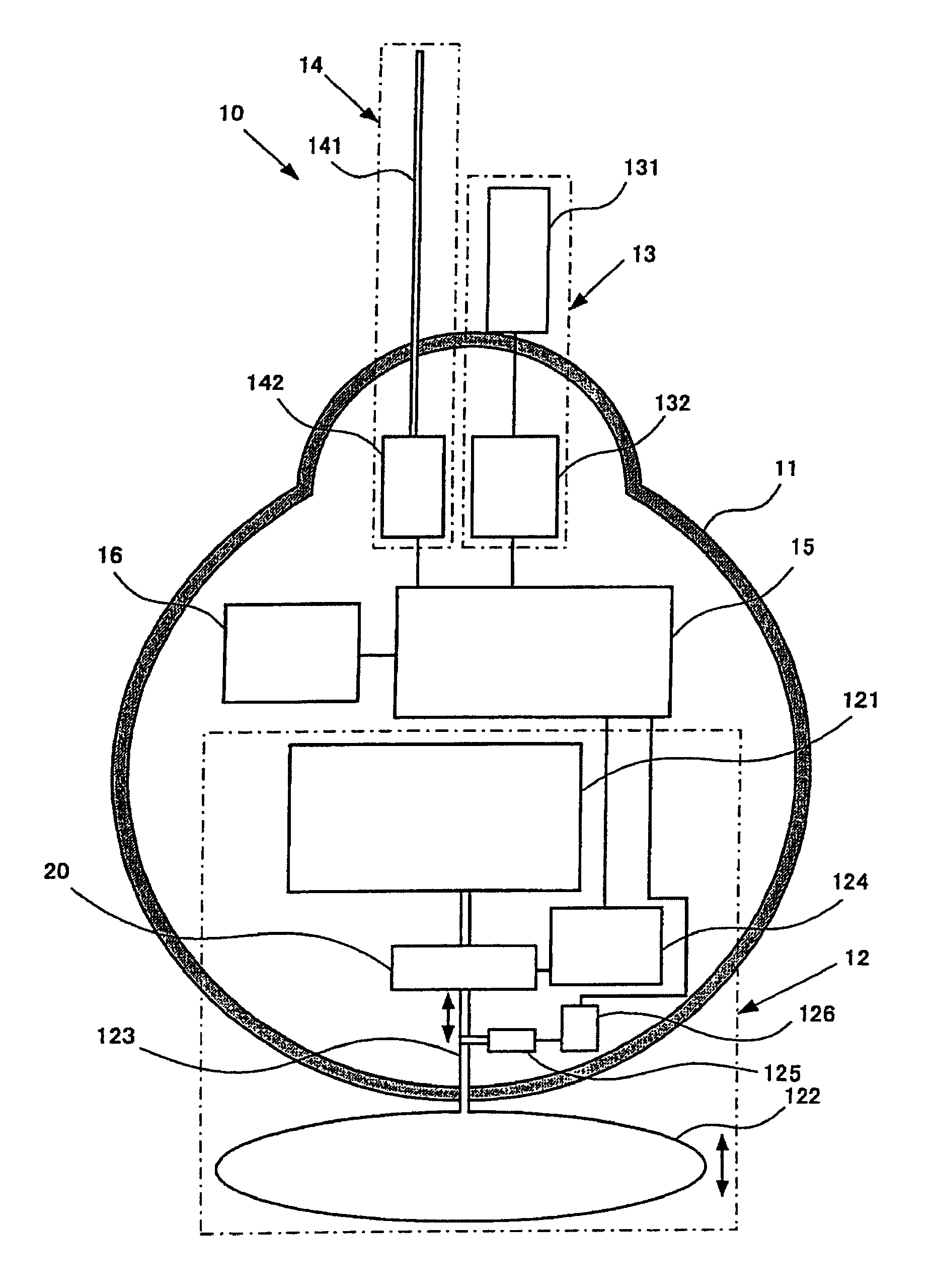
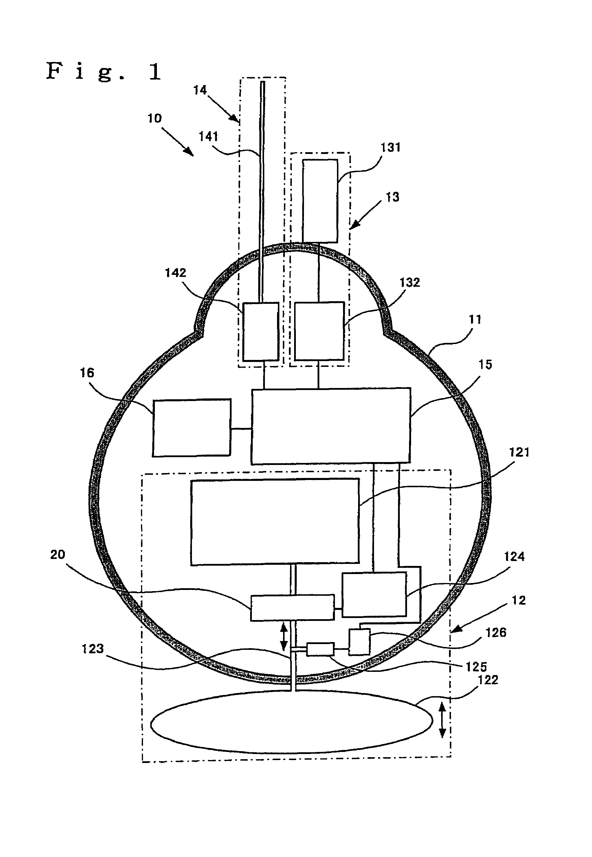
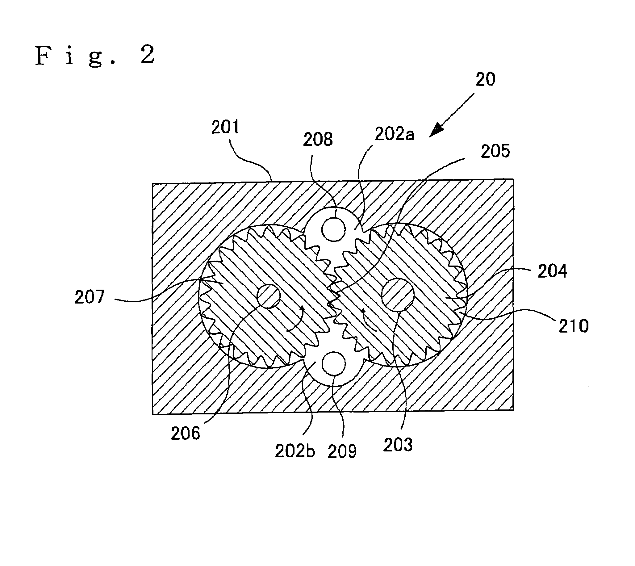
[0086]FIG. 1 is a cross-sectional view illustrating the construction of an exemplary profiling float according to the present invention taken along a major axis of a float chamber, and FIG. 2 is a cross-sectional view illustrating the construction of a gear pump in a section perpendicular to a rotational shaft of the gear.

[0087]In the embodiment illustrated, the profiling float 10 is equipped with, as a housing, a substantial sphere-type float chamber 11 made of, for example, a reinforced resin, which forms an airtight internal space, and is constructed by a buoyancy controlling mechanism 12 for controlling the degree of buoyancy acting on the whole of the profiling float 10, a measuring mechanism 13 for measuring various kinds of information, including a seawater pressure, in the sea, a data transmitting mechanism 14 for radio-transmitting the electronic data obtained by the measuri...


PUM


Abstract

Provided is a profiling float that can minutely and surely control effective buoyancy acting on the float in itself, and usage of the profiling float.The profiling float according to the present invention is equipped with a float chamber forming an airtight internal space, a fluid storage part provided in the float chamber and storing a fluid for control of buoyancy, a bladder provided at the exterior of the float chamber, in the interior of which the fluid for control of buoyancy is filled to change a volume thereof, thereby controlling buoyancy acting on the profiling float, a pump mechanism for transferring the fluid for control of buoyancy between the bladder and the fluid storage part, and a driving source for driving the pump mechanism, wherein the pump mechanism is composed of a gear pump.

Description

[0001]This application is a U.S. National Phase Application under 35 USC 371 of International Application PCT / JP2005 / 022542 filed Dec. 8, 2005.TECHNICAL FIELD[0002]The present invention relates to a profiling float used in, for example, a high-performance marine monitoring system and usage of the profiling float.BACKGROUND ART[0003]In recent years, it has been necessary to clarify and grasp environmental variation mechanisms, for example, a mechanism of heat transport in ocean, on a global scale in order to cope with environmental problems such as global warming. A high-performance marine monitoring system for that purpose is being pushed forward. In such a high-performance marine monitoring system, it is necessary to monitor vertical structures of, for example, physical parameters such as sea temperatures and chemical parameters such as salinity concentrations from a sea depth of about 2,000 m to a sea level, i.e., changes in various parameters in a direction of the depth of the se...

Claims


Application Information

Patent Timeline
Patent Type & Authority Patents(United States)
IPC IPC(8): B63B22/20
CPCB63B22/20B63C11/48B63C11/00
Inventor YOSHIDA, MASAHIROTAKEUCHI, KENSUKEKURODA, YOSHIFUMISHIKAMA, NOBUYUKIANDO, KENTAROKOBAYASHI, TAIYOHOSODA, SHIGEKI
Owner NAT INST FOR MATERIALS SCI
Why Eureka
Try Eureka