Catheter guide wire especially for percutaneous transluminal coronary angioplasty

a technology of catheter guide wires and percutaneous transluminal coronary angioplasty, which is applied in the direction of guide wires, sensors, medical science, etc., can solve the problems of increased susceptibility of the wire shaft to notch breakage, and injury to the vessel wall

Inactive Publication Date: 2010-04-20
BIOTRONIK AG
View PDF33 Cites 21 Cited by
  • Summary
  • Abstract
  • Description
  • Claims
  • Application Information

AI Technical Summary

Problems solved by technology

Catheter guide wires of this type pose the problem that the wire, especially at its distal end, needs to be as flexible as possible on one hand in order to ensure the most atraumatic insertion of the wire into coronary vessels, and in the process a smooth passage through narrow points and bends in the vasculature being targeted; on the other hand, the markers that are used to identify the guide wire in the case of an X-ray monitoring during the performance of a PTCA, require a certain material volume in order to keep the achievable contrast in the X-ray image at a suitable level.
Sharp inner corners would eventually lead to an increased susceptibility of the wire shaft to notch breakage.
In this respect no interfering edges result on the product, especially after the grinding and polishing of such a guide wire with marker, which could cause injuries to the vessel wall—so-called “dissections”—while the wire is being inserted.

Method used


Image

  • Catheter guide wire especially for percutaneous transluminal coronary angioplasty
  • Catheter guide wire especially for percutaneous transluminal coronary angioplasty

Examples


Embodiment Construction

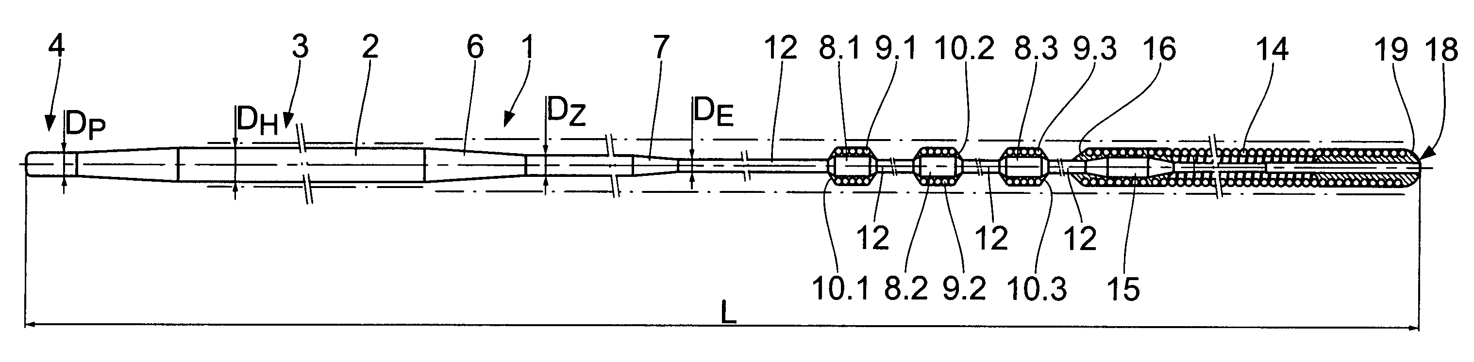
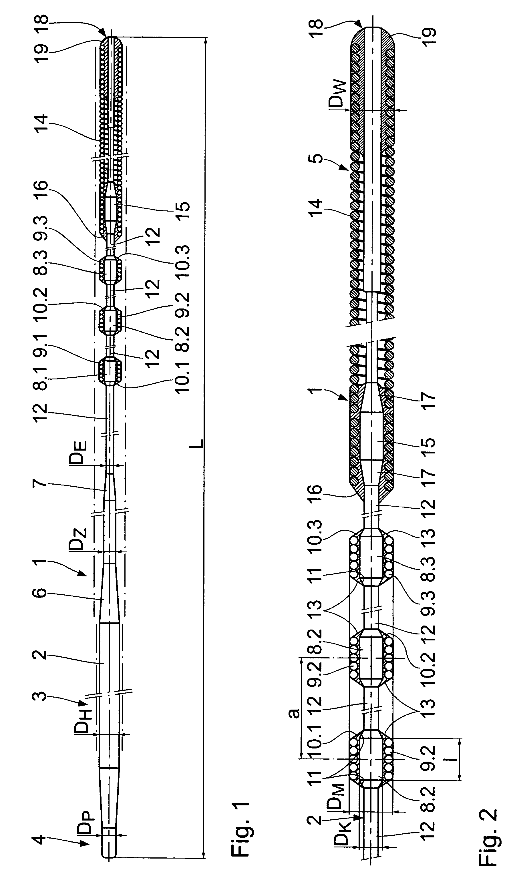
[0013]As is apparent from FIG. 1, the guide wire, which has been marked in its entirety with 1, incorporates an elongated wire shaft 2 of medical-grade stainless steel. Shaft sections of varying diameters are provided over its total length L of, for example, 1750 mm. The wire shaft 2 thus has at its proximal end 3, for example, a conically narrowing end section, whose outside diameter DP of, for example 0.223 mm, is significantly smaller than the main diameter DH of the wire shaft 2 of 0.36 mm. The conically narrowing proximal end 3 of the wire shaft 2 serves to attach a wire extension.

[0014]In the distal end zone, whose length may be altogether approximately 300 mm, which is located adjacent to the distal end 5 of the guide wire 5, the wire shaft 2 is reduced in its thickness from its main diameter DH over conical ramps 6, 7 to an intermediate diameter DZ of approximately 0.2 mm and to a final diameter DE of approximately 0.12 mm. In the process, however, core sections 8.1, 8.2, 8....


PUM


Abstract

A catheter guide wire, especially for percutaneous transluminal coronary angioplasty, comprises an elongated wire shaft of a flexible material having a proximal and a distal end and disposed on the wire shaft at least one radiopaque, sleeve-like marker adjacent to the distal end. The at least one marker is disposed on a core section of the wire shaft, said core section being widened in its diameter relative to the diameter of the adjoining shaft sections.

Description

FIELD OF THE INVENTION[0001]The invention relates to a catheter guide wire, especially for percutaneous transluminal coronary angioplasty (PTCA).BACKGROUND OF THE INVENTION[0002]Catheter guide wires of a known type have an elongated wire shaft of a flexible material with a proximal and a distal end. In the distal end area, one or more radiopaque, sleeve-like markers are disposed on the wire shaft, which have essentially two functions. On one hand, the position of the guide wire tip must be easily visible on an x-ray monitor—for example by means of an elongated marker coil directly at the distal end of the guide wire—while the catheter is being applied. On the other hand, a length measurement of a stenosis to be treated can be performed on the X-ray monitor, for example, with the aid of multiple markers that are equidistantly spaced adjacent to the distal end.[0003]Guide wires of this type are known in their fundamental design from a multitude of printed publications. U.S. Pat. No. 5...

Claims


Application Information

Patent Timeline
Patent Type & Authority Patents(United States)
IPC IPC(8): A61B5/00A61M25/01A61M25/09A61M25/095
CPCA61M25/09A61M25/0108A61M2025/09166
Inventor HOFMANN, EUGENWINTSCH, CHRISTOPH
Owner BIOTRONIK AG
Why Eureka
Try Eureka