Cryotreatment device and method

a cryotherapy and device technology, applied in the field of cryotherapy devices and methods, can solve the problems of irritating the wall of the artery in which they are implanted, affecting the goal of the angioplasty procedure, and in whole or in part, so as to reduce the adverse reaction of medical procedures affecting, and reduce the effect of any injury respons

Inactive Publication Date: 2007-05-22
BOSTON SCI SCIMED INC
View PDF48 Cites 205 Cited by
  • Summary
  • Abstract
  • Description
  • Claims
  • Application Information

AI Technical Summary

Benefits of technology

[0007]The present invention includes devices and methods for reducing adverse reactions to medical procedures impacting body vessels such as blood vessels by cooling the effected vessel regions. The invention includes methods and devices for cooling blood vessel sites having a lesion which are to be impacted by angioplasty. The vessel wall cooling can be performed before, during, and / or after the angioplasty procedure and any combinations thereof. The cooling is believed to lessen any injury response which may be caused by the angioplasty, as the body may interpret the angioplasty procedure as an injury and react in ways that can cause restenosis.
[0008]One set of methods according to the present invention include distally advancing a tubular catheter having numerous radially outwardly pointing coolant distributing orifices supplied by a coolant lumen in fluid communication with a proximal coolant source. The coolant can be sprayed in the direction of the vessel wall and toward the lesion. One device used includes an expandable occlusion device for expanding against the vessel walls and greatly reducing, if not stopping, blood flow during the procedure. Occluding the blood vessel can reduce the vessel wall warming which is caused by blood flow through the vessel. Occluding the vessel also lessens the removal of coolant by the flowing blood. Occluding devices can be disposed on the cooling catheter shaft proximally and / or distally of the coolant distributing orifices. Inflatable occluding devices can be inflated by either the coolant fluid or by an inflation fluid other than the coolant. The coolant can be liquid, gas, or liquid that changes phase to gas during the cooling process.

Problems solved by technology

In some cases, however, the goal of the angioplasty procedure is, in whole or in part, frustrated by complete or partial reclosure of the artery at the lesion.
Although stents have been found to be highly effective, they may irritate the wall of a artery in which they are implanted.
Heating of the lesion, however, is believed to cause an injury response which may cause some restenosis.

Method used


Image

  • Cryotreatment device and method
  • Cryotreatment device and method
  • Cryotreatment device and method

Examples


Embodiment Construction

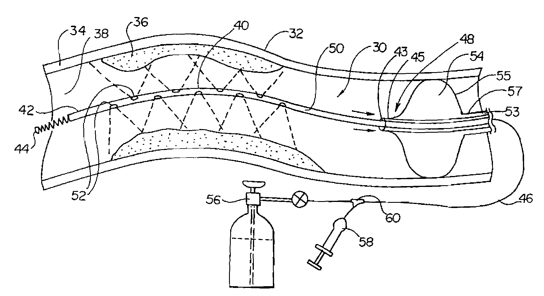
[0034]FIG. 1 illustrates a vessel cooling device 30 disposed within a body blood vessel 32 having a vessel wall 34, a lumen 38 therethrough, and a stenosis, lesion, or plaque 36 partially occluding the vessel lumen and extending over a length of vessel. In the embodiment illustrated, cooling device 30 includes a tubular shaft 48 having a proximal region 46, distal region 40, a distal end 42, and a distal tip 44. Shaft 48 includes a coolant tube 50 having a lumen therethrough and a plurality of coolant delivery orifices 52 disposed longitudinally and radially about the shaft distal region. The coolant is illustrated as spraying directly on the lesion. Cooling device 30 also includes an occlusion device 55 for occluding the vessel lumen. In the embodiment illustrated, an annular exhaust lumen 43 is defined between coolant tube 50 and a coaxially disposed exhaust tube 45. Exhaust tube 45 can be used to remove coolant from the vessel, in either liquid or gaseous form. In this embodiment...


PUM


Abstract

Devices and methods for cooling vessel walls to inhibit restenosis in conjunction with medical procedures such as coronary artery angioplasty. Stenosed vessel walls can be cooled prior to angioplasty, after angioplasty, or both. The invention is believed to inhibit restenosis through cooling to a temperature near freezing, preferably without causing substantial vessel wall cell death. One catheter device includes a distal tube region having coolant delivery holes radially and longitudinally distributed along the distal region. In some devices, holes spray coolant directly onto the vessel walls, with the coolant absorbed into the blood stream. In other embodiments, a balloon or envelope is interposed between the coolant and the vessel walls and the coolant returned out of the catheter through a coolant return lumen. Some direct spray devices include an occlusion device to restrict blood flow past the region being cooled. Pressure, temperature, and ultrasonic probes are included in some cooling catheters. Pressure control valves are included in some devices to regulate balloon interior pressure within acceptable limits. In applications using liquid carbon dioxide as coolant, the balloon interior pressure can be maintained above the triple point of carbon dioxide to inhibit dry ice formation. Some cooling catheters are coiled perfusion catheters supporting longer cooling periods by allowing perfusing blood flow simultaneously with vessel wall cooling. One coiled catheter is biased to assume a coiled shape when unconstrained and can be introduced into the body in a relatively straight shape, having a stiffening wire inserted through the coil strands.

Description

RELATED APPLICATIONS[0001]The present application is related to U.S. patent application Ser. No. 09 / 229,080, filed Jan. 12, 1999, entitled CRYOPLASTY DEVICE AND METHOD; which is a divisional of U.S. patent application Ser. No. 08 / 812,804, filed Mar. 6, 1997, entitled CRYOPLASTY DEVICE AND METHOD, now issued as U.S. Pat. No. 5,868,735.FIELD OF THE INVENTION[0002]The present invention is related generally to medical devices and methods. More specifically, the present invention relates to devices and methods for cooling internal body locations. The present invention includes methods for cooling stenosed blood vessel regions prior to and subsequent to angioplasty to inhibit restenosis.BACKGROUND OF THE INVENTION[0003]Conventional angioplasty has been performed for several decades, prolonging the lives of an ever-increasing number of patients. Angioplasty procedures involve the dilatation of a balloon placed across a lesion in a coronary artery. Dilatation of the balloon in turn dilates ...

Claims


Application Information

Patent Timeline
Patent Type & Authority Patents(United States)
IPC IPC(8): A61B18/18A61B17/00A61B17/22A61B18/00A61B18/02A61B19/00A61F2/958A61F7/12A61M1/36A61M25/00A61M39/00
CPCA61B18/02A61F7/123A61F7/10A61F2007/0063A61B2017/00867A61B2017/22002A61B2017/22051A61B2017/22067A61B2018/00041A61B2018/00196A61B2018/0022A61B2018/0212A61B2018/0275A61B2018/0287A61B2018/1861A61B2019/4063A61B2019/464A61B2019/5278A61F2007/0001A61B2017/00243A61B2090/0463A61B2090/3782A61B2090/064
Inventor LAFONTAINE, DANIEL M.
Owner BOSTON SCI SCIMED INC
Why Eureka
Try Eureka