Light emitter assembly

a technology of light emitting assemblies and parts, which is applied in the direction of point-like light sources, semiconductor devices of light sources, lighting and heating apparatus, etc., can solve the problems of significant heat generation, achieve simple design, reduce the number of parts, and satisfy the light dispersion or radiation pattern.

Active Publication Date: 2010-04-20
HONG KONG APPLIED SCI & TECH RES INST
View PDF37 Cites 16 Cited by
  • Summary
  • Abstract
  • Description
  • Claims
  • Application Information

AI Technical Summary

Benefits of technology

[0022]This invention provides an light emitter assembly having satisfactory light dispersion or radiation pattern and a simple design with a reduced number of parts to minimize manufacturing costs. Heat is efficiently dispersed into the housing and the spacings between the ribs of the housing, as well as between the substrates themselves, enhance the heat transfer rate through natural convection in different orientations of the assembly.

Problems solved by technology

High output LEDs, particularly when a large number are used on a common support, produce a significant amount of heat.

Method used


Image

  • Light emitter assembly
  • Light emitter assembly
  • Light emitter assembly

Examples


Embodiment Construction

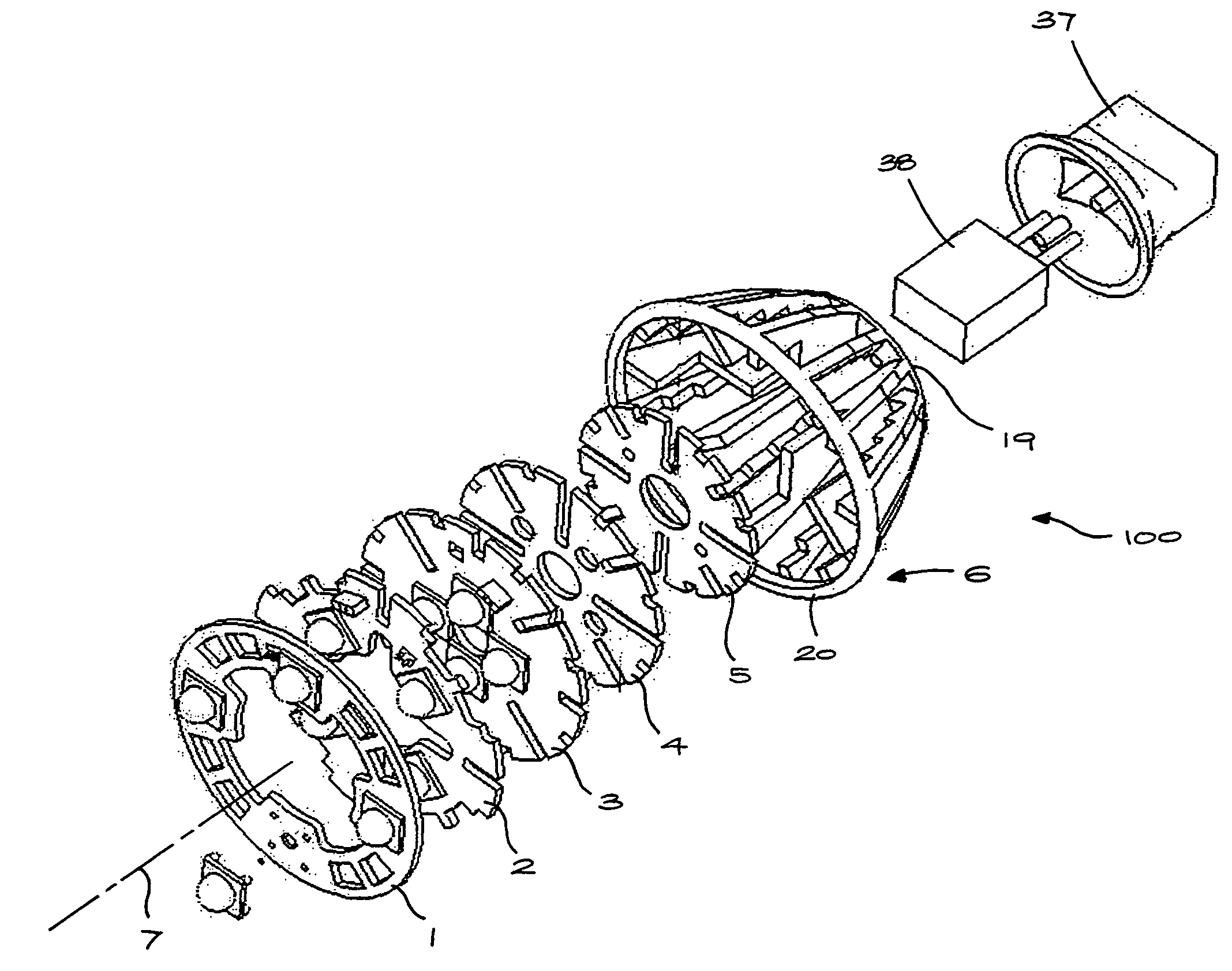
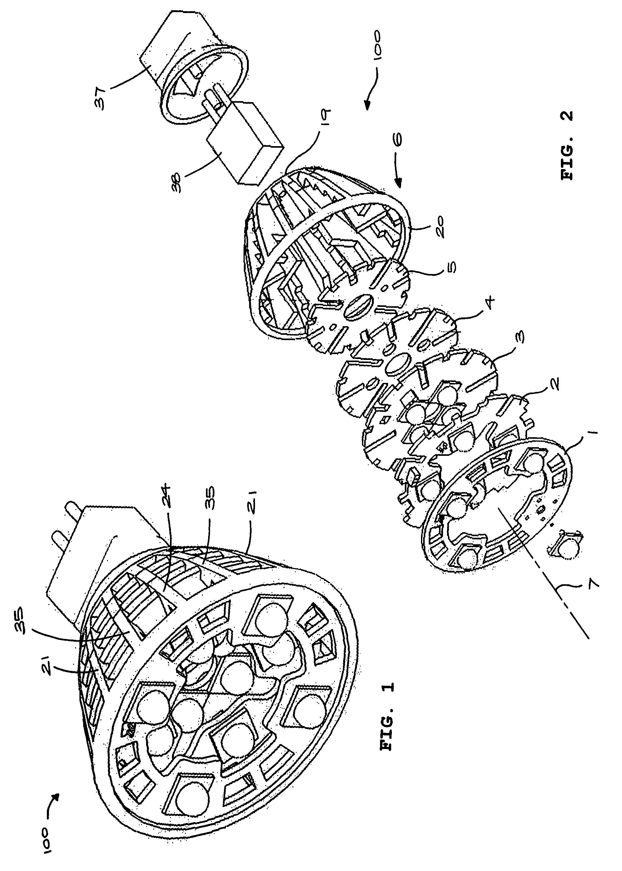
[0033]Referring to FIGS. 1 and 2, a light emitter assembly 100 includes three light emitter substrates 1, 2, 3 and two heat dissipating members 4, 5 which are stacked in a housing 6. The components 1-5 are substantially parallel, extending transversely relative to a central longitudinal axis 7. In the embodiment illustrated the LED substrates 1, 2, 3 and heat dissipating members 4, 5 are in a generally planar ring shape, but it will be understood that different shapes will be equally applicable depending upon the required application of the assembly.

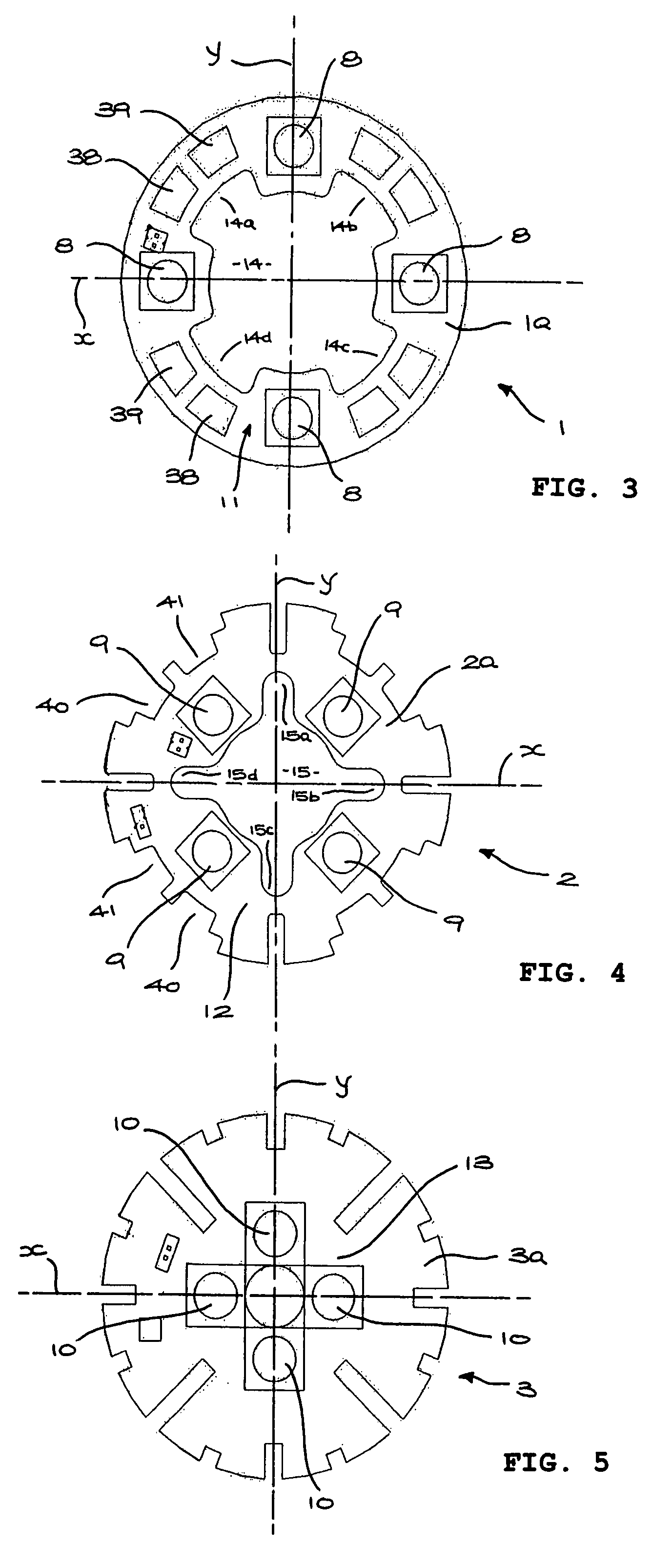
[0034]Each LED substrate 1, 2, 3 has an outer surface 1a, 2a, 3a and an opposing inner surface 1b, 2b, 3b. Four LEDs 8, 9, 10 are mounted on the respective outer surfaces 1a, 2a, 3a equally angularly spaced on respective pitch circles 11, 12, 13 centred on the central axis 7 and emitting light substantially parallel to the axis 7.

[0035]The LEDs on the three substrates 1, 2, 3 are offset radially, the pitch circle diameter 11 exceeding pi...


PUM


Abstract

A plurality of disc-shaped substrates carry light emitters and are axially stacked, spaced apart, in a metal housing to dissipate the heat produced by the light emitters. The housing comprises mutually connected elongate planar ribs that abut the light emitters or substrates for thermally connecting the light emitters to the housing. The ribs have shoulders. The substrates are received between the ribs and abut the shoulders. The shoulders are positioned proximate each light emitter in intimate contact with the substrate for efficient heat dissipation.

Description

PRIOITY CLAIM[0001]This patent claims priority from the earlier filed Hong Kong Patent Application No. 06112953.4 filed Nov. 24, 2006, by inventors Kai Chiu Wu, Ming Lu, and Chak Hau Pang.TECHNICAL FIELD[0002]This invention relates to light emitting assemblies having heat dissipating supports for reducing the operating temperature of the assembly.BACKGROUND OF THE INVENTION[0003]Light sources comprising assemblies of light emitters such as light emitting diodes (LEDs) are finding increasing application in mass production applications because of their high efficiency and long life. One such application is light sources for replacing florescent and incandescent lights and the like.[0004]High output LEDs, particularly when a large number are used on a common support, produce a significant amount of heat. If elevated temperatures are then produced, the life of the LEDs is reduced. In practice, it is desirable that the LED be placed into contact with heat dissipation surfaces to effectiv...

Claims


Application Information

Patent Timeline
Patent Type & Authority Patents(United States)
IPC IPC(8): H01L23/34F21Y101/00
CPCF21K9/13F21Y2101/02F21Y2111/008F21V29/767F21V29/773F21V29/83H05K2201/10295H05K1/0203H05K1/144H05K2201/09027H05K2201/09063F21K9/23F21Y2107/60F21Y2115/10
Inventor WU, KAI CHIULU, MINGPANG, CHAK HAU
Owner HONG KONG APPLIED SCI & TECH RES INST
Why Eureka
Try Eureka