

Method and system to improve atomization and combustion of heavy fuel oils
- Summary
- Abstract
- Description
- Claims
- Application Information
AI Technical Summary
Benefits of technology
Problems solved by technology
Method used
Image

Examples
Embodiment Construction
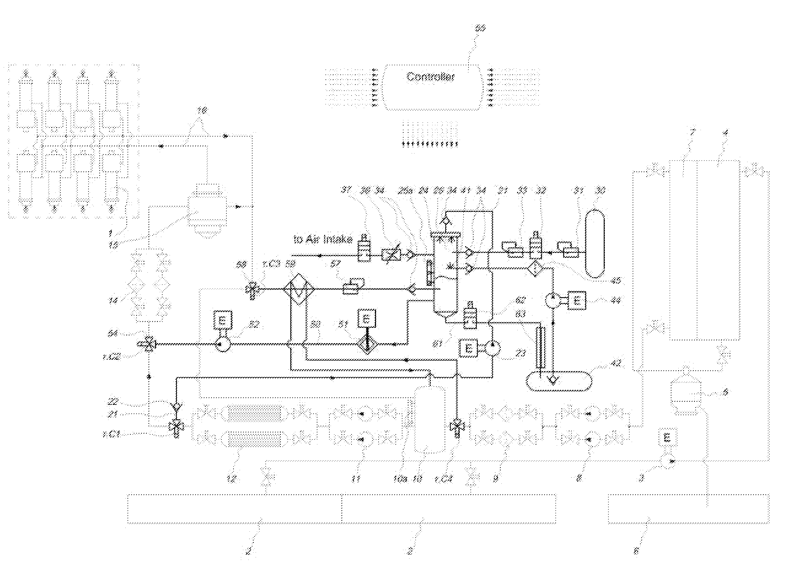
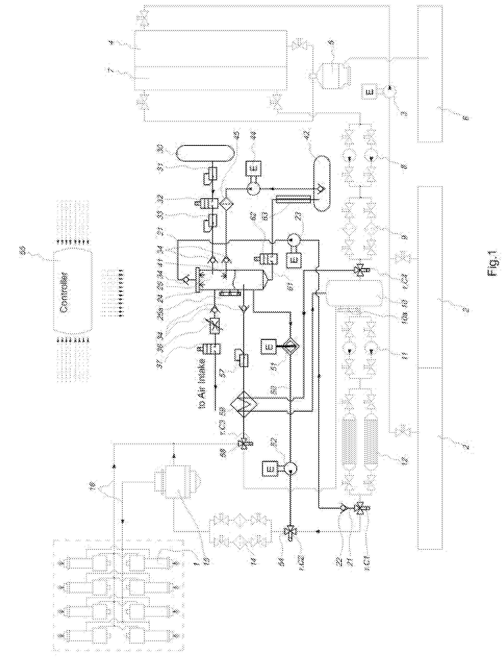
[0044]Referring to the FIG. 1 the base fuel supply system of a marine engine 1 operates as follows: the heavy fuel oil (hereinafter, HFO) is transferred by a transfer pump 3 from a fuel bunker tank 2 to a fuel settlings tank 4. From the fuel settlings tank 4 the HFO is supplied to a fuel purifier 5 to separate clumps and impurities having a size more than 10 microns that drain to a sludge tank 6. The ready to use purified HFO is transferred to a fuel service tank 7. Fuel feeding pumps 8 pump the HFO to a mixing tank 10 through first stage fuel filters 9. Fuel circulation Pumps 11 pump the HFO through fuel heaters 12 and second stage fuel filters 14 to a fuel injection pump 15, which delivers it to fuel injectors of the marine engine 1 under injection pressure of 300 to 350 bar. To provide the required viscosity and optimal atomization of the HFO in combustion chambers it is heated by fuel heaters 12 to a temperature of at least 275° F. (135° C.). The fuel is supplied to the engine i...
PUM
 Abstract
Description
Claims
Application Information