Methods of underground formation consolidation

a technology of underground formation and consolidation, applied in the direction of fluid removal, chemistry apparatus and processes, borehole/well accessories, etc., can solve the problems of reducing the effectiveness of gravel pack and screen, sand production is undesirable, and gravel pack and screen may be plugged

Inactive Publication Date: 2010-04-27
SUPERIOR ENERGY SERVICES LLC
View PDF13 Cites 14 Cited by
  • Summary
  • Abstract
  • Description
  • Claims
  • Application Information

AI Technical Summary

Problems solved by technology

Production of sand is undesirable since it erodes surface and subterranean equipment, and it must be removed from the produced fluids before they can be processed.
Over time, the gravel pack and the screen may be plugged by scale or particles, or badly eroded by the sand and other particulates in the produced fluids.
This reduces the effectiveness of the gravel pack and screen and may actually shut down the production if the gravel pack and / or screen becomes plugged with sand or formation fines.
Additionally, the presence of the metal screen in the well inhibits reentry of drills and other tools into the wellbore and the metal screen can be difficult and costly to remove.
Resin-based consolidation systems may be complicated to apply, especially those involving multiple treatment stages, and the treatment results may be erratic.
And, if they do combine, good mixing of the components is not assured.
This difficulty helps explain the erratic and unreliable results that operators have experienced using such multi-stage consolidating fluids.
The efficiency of mixing or blending is also questionable.
Though some of the above-mentioned techniques have achieved a degree of commercial success, many of them have been hindered by technical and / or cost limitations.

Method used


Image

  • Methods of underground formation consolidation
  • Methods of underground formation consolidation
  • Methods of underground formation consolidation

Examples


example 1

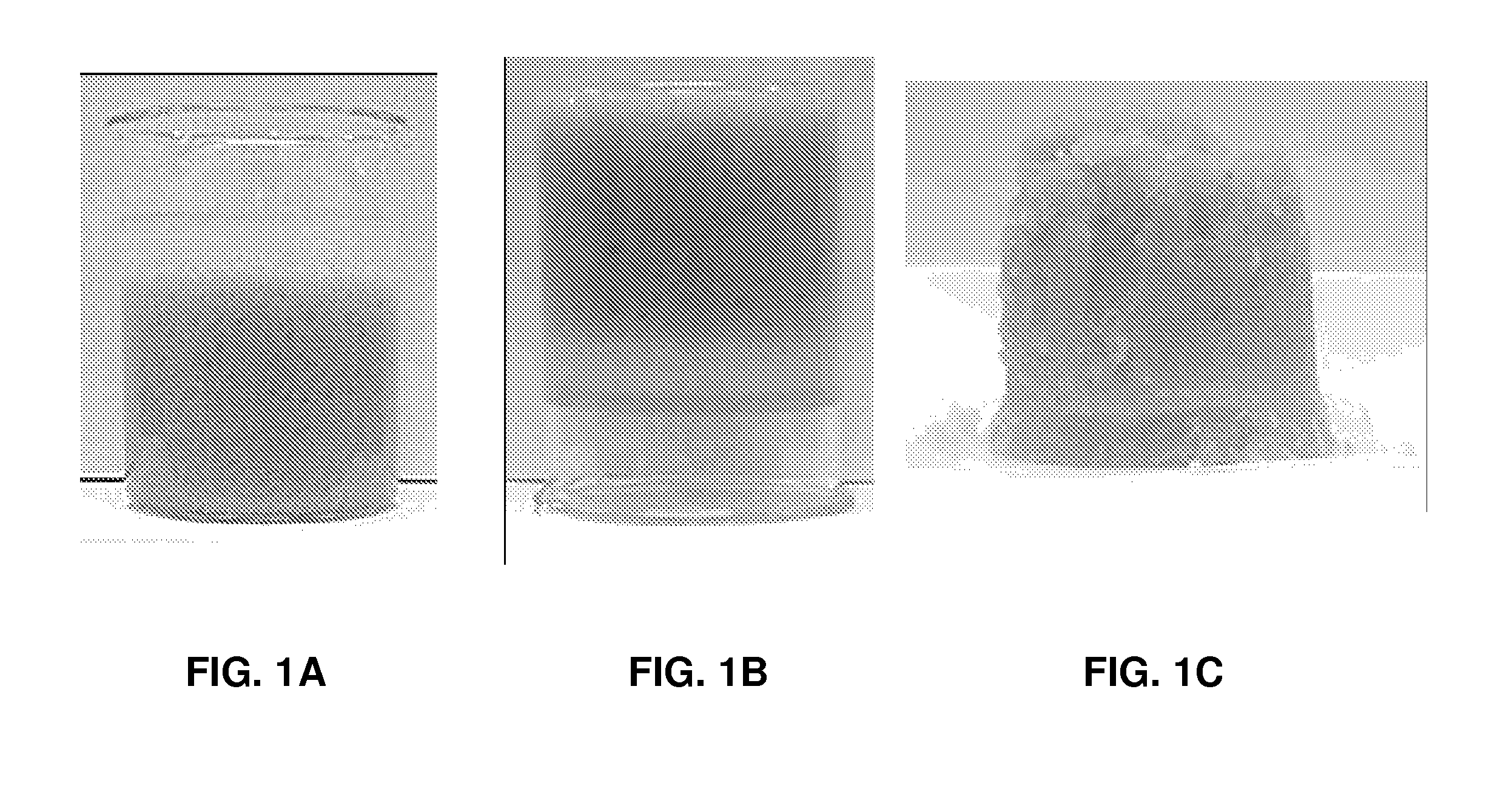
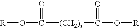
[0040]Shown in FIG. 1A is a photograph of a beaker containing PERM-PLUG™, available from Baker Oil Tools. This beaker contains 20 / 40 mesh (425 / 850 micron) sand together with 40 ml 6.7 by % FLC-1L and 1.5 ml FLH-1L at 70° F. (21° C.) before gelation. FLC-1L is a 37.5% by weight (bw) sodium silicate solution (40˜42° Bé from Fisher Scientific). FLH-1L is DBE, a dibasic ester mixture of dimethyl glutarate, dimethyl adipate and dimethyl succinate, available from DuPont. The solution formulation may be found in U.S. Patent Application Publication 2004 / 0031611 A1, previously incorporated herein by reference.

[0041]After gelling (or gelation) of the composition, the beaker was inverted and the photograph of FIG. 1B was taken, the sand consolidated by the gel of the composition remained in the bottom of the beaker.

[0042]Shown in FIG. 10 is the consolidated sand after the beaker has been removed. It may be seen that the 20 / 40 mesh (425 / 850 micron) sand used in Example 1 was successfully, compl...

example 2

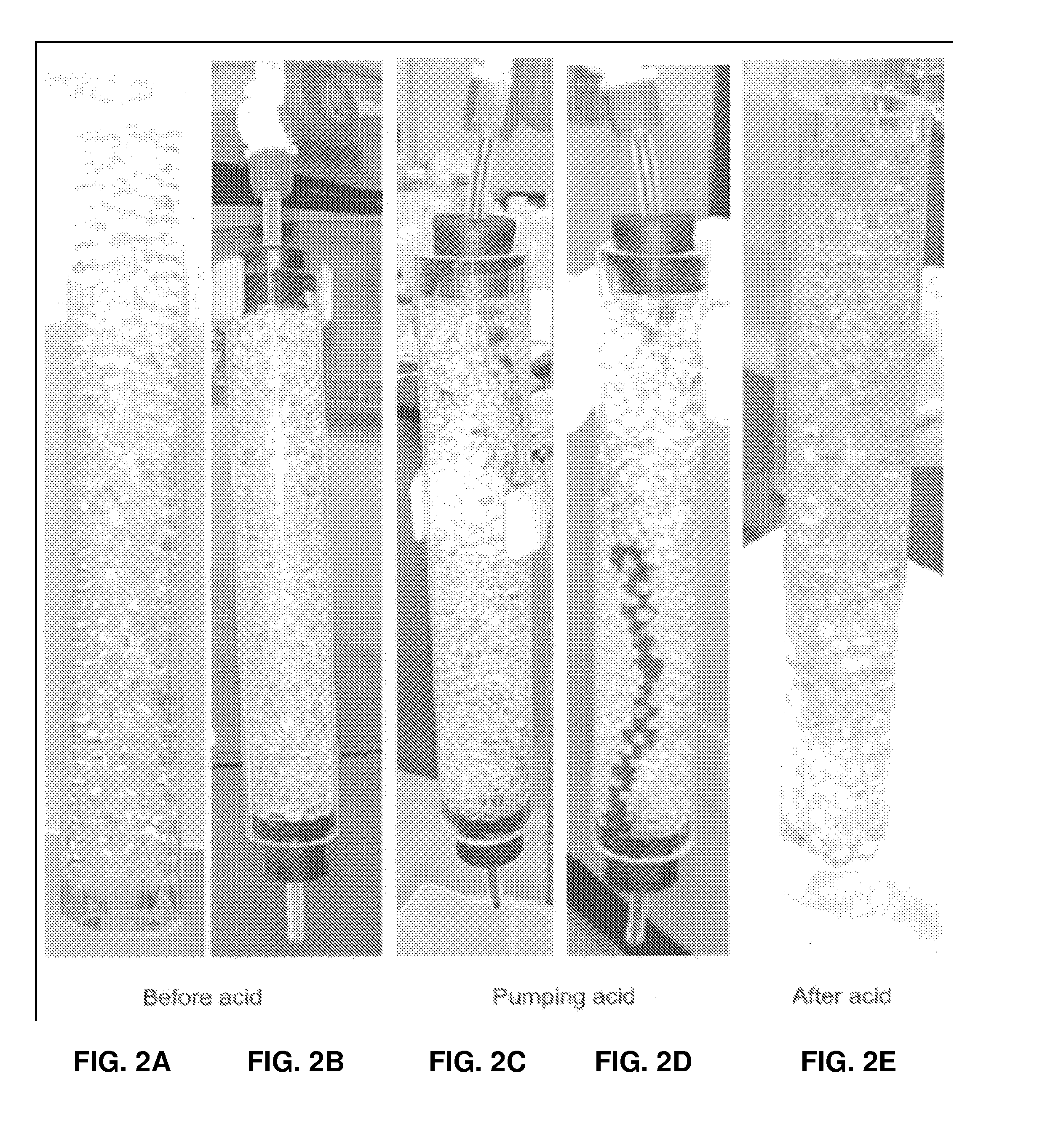
[0043]In the photograph of FIG. 2A is shown a 1-inch (2.5 cm) ID and 18 inches (46 cm) long acrylic tube filled with 6-mm diameter glass beads, used to simulate an unconsolidated near-wellbore formation. Unconsolidated formation sand is usually less than 20 mesh (850 micron), which is much smaller than 6-mm diameter glass beads. This Example indicates that the silica gel has enough strength to hold the bigger beads, which means it is effective and easier to consolidate formation sands using the methods described herein. The composition used in Example 1 was then introduced into the acrylic tube and the glass beads were consolidated with the silica gel. After consolidation, the top and bottom ends of the tube were sealed with rubber connections and ports for introducing acid flow into the top of the tube and removing the acid from the bottom of the tube. This apparatus is shown in FIG. 2B.

[0044]Shown in FIG. 2C is acid being pumped through the acrylic tube; the acid was dyed red and ...


PUM


Abstract

Unconsolidated formation sand in the near wellbore region may be uniformly consolidated using a system including a sodium silicate solution and a hardener, such as at least one dialkyl ester of a dicarboxylic acid. Subsequently, a low concentration acid, such as hydrofluoric (HF) acid, is pumped through and into the consolidated sand to create channels or passageways to connect the formation hydrocarbons with the wellbore for production of the hydrocarbons through the wellbore. Hydrofluoric acid may be generated in situ by hydrolyzing a substance to hydrofluoric acid where the substance may include ammonium bifluoride, ammonium fluoride, alkali metal fluorides, alkali metal bifluorides, transition metal fluorides, and the like, and mixtures thereof. The acid may instead or additionally include organic acids and other mineral acids.

Description

TECHNICAL FIELD[0001]The present invention relates to methods and compositions to consolidate sand in the near wellbore region of a subterranean formation containing unconsolidated sand, and more particularly relates, in one embodiment, to such methods where acids are subsequently introduced to generate channels through the consolidated sand between the formation hydrocarbons and the wellbore.TECHNICAL BACKGROUND[0002]Hydrocarbon fluids, such as oil and natural gas, and other desirable formation fluids are obtained from a subterranean geologic formation, i.e., a reservoir, by drilling a well that penetrates the formation zone that contains the desired fluids. Once a wellbore has been drilled, the well must be completed, which involves the design, selection, and installation of equipment and materials in or around the wellbore for conveying, pumping, or controlling the production or injection of fluids.[0003]When the subterranean formation is “soft” or poorly consolidated, small part...

Claims


Application Information

Patent Timeline
Patent Type & Authority Patents(United States)
IPC IPC(8): E21B33/13E21B43/27
CPCC09K8/56E21B43/025C09K8/72
Inventor HUANG, TIANPING
Owner SUPERIOR ENERGY SERVICES LLC
Why Eureka
Try Eureka