
Microscopic cell observation and inspection system using a plurality of observation methods

a cell observation and inspection system technology, applied in the field of microscope cell observation and inspection system using a plurality of observation methods, can solve the problems of poor specimen manipulation, wave attenuation exponentially, and limited sample flexibility, so as to facilitate sample manipulation, reduce scattered light, and high sn-ratio observation

Inactive Publication Date: 2010-04-27
HAMAMATSU UNIV SCHOOL OF MEDICINE +1
View PDF23 Cites 9 Cited by
  • Summary
  • Abstract
  • Description
  • Claims
  • Application Information

AI Technical Summary

Benefits of technology

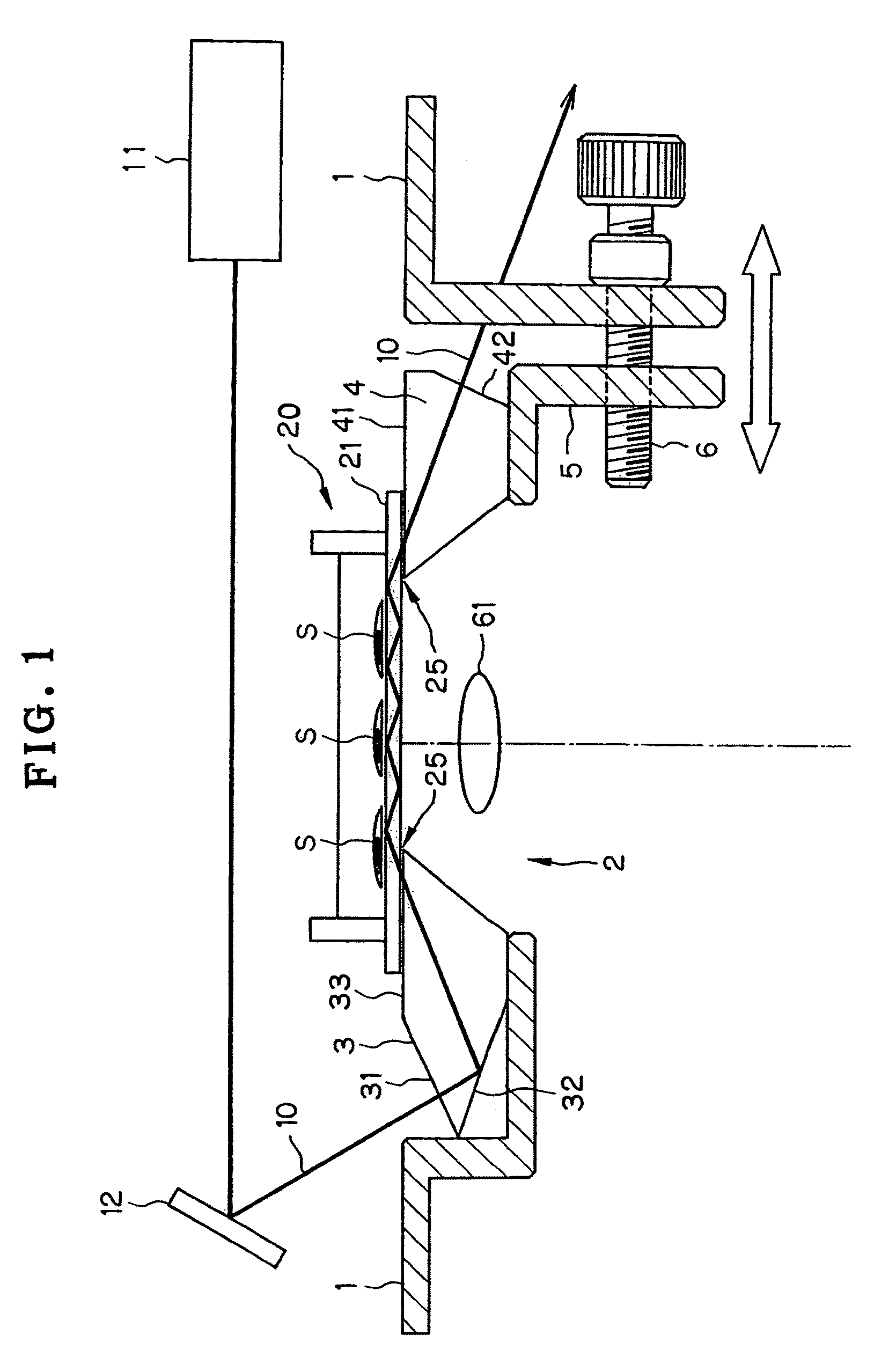
[0015]In view of such problems with the prior art, the invention has for its object the provision of a microscopic cell observation and inspection system using a plurality of observation methods, which uses a total internal reflection illuminator that enables an observation position to be freely changed on any slide glass without recourse to any special one, makes sure high SN-ratio observation with much more reduced scattered light and facilitates specimen manipulation to make high-sensitivity, fast detection of as many as several hundreds or more of cell reactions on the same slide glass.
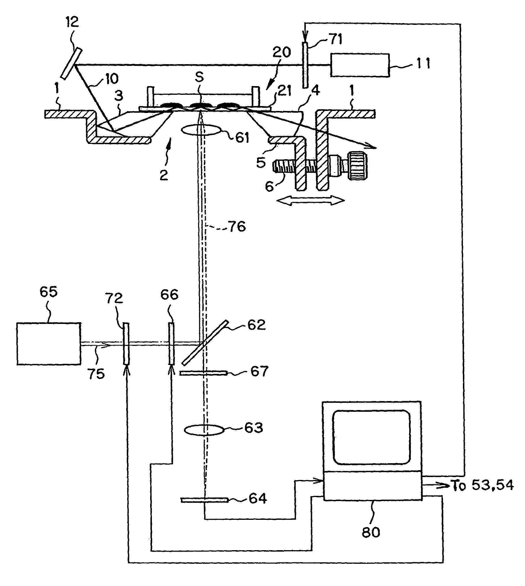
[0034]In a preferable embodiment of the invention, said optical path splitter comprises a dichroic mirror and is operable to prevent light having a wavelength of illumination light from said evanescent wave-generation light source and light having a wavelength of illumination light from said excitation light source for a drop fluorescence microscope from arriving at said optical path on the imaging device side but allow only fluorescence emanating from the cell sample to arrive at said optical path on the imaging device side.
[0056]According to the invention, the total internal reflection sample illuminator is set up such that an observation position on any slide glass can be freely changed without recourse to any special one, high SN-ratio observation is enabled with much more reduced scattered light and sample manipulation is facilitated; it is possible to make high-sensitivity, fast observation and inspection of as many as several hundreds or more of cell reactions on the same slide glass using a plurality of observation methods such as a drop fluorescence microscope technique and a confocal fluorescence microscope technique, and make a lot of contributions to drug design screening, and so on.

Problems solved by technology

However, there are some evanescent waves unavoidably generated from the interface to the side of the substance 1 having a lower refractive index, which waves attenuate exponentially.
However, the space above the objective lens is closed up, resulting in very poor specimen manipulation and more limited degrees of sample flexibility.
These methods take hold of a free space above the sample and facilitates low-magnification observation, but because the slide glass is limited to a small thickness (0.17 mm in the former, and 0.2 mm in the latter), they offer some problems: a lot more multiple total internal reflections, the occurrence of scattered light due to total internal reflection, attenuation of guided light, the likeliness of the specimen to discolor due to fluorescence, and lower SN ratios.
Further, the positions of incidence and radiation of laser light remain fixed, rendering it hard to adjust an optical path for laser light, and making sample manipulation not easy because of the need of moving the objective lens to change a specimen observation position.
Yet further, much work is needed with decreased versatility, because of the need of bonding the prisms to the slide glass for each sample.

Method used


Image

  • Microscopic cell observation and inspection system using a plurality of observation methods
  • Microscopic cell observation and inspection system using a plurality of observation methods
  • Microscopic cell observation and inspection system using a plurality of observation methods

Examples


Embodiment Construction

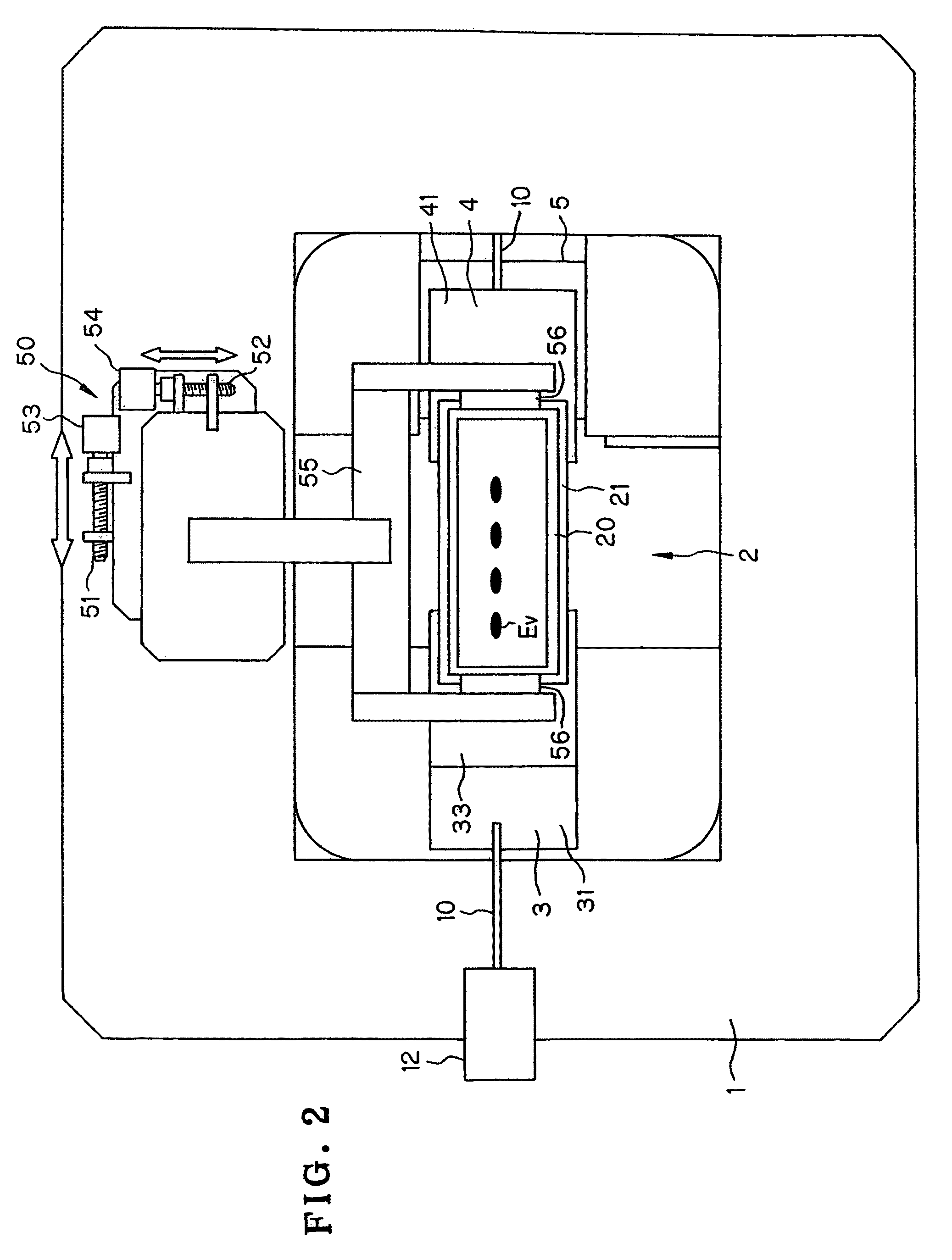
[0072]The microscopic cell observation and inspection system using a plurality of observation methods according to the invention is now explained with some embodiment and examples. Before that, the total internal reflection sample illuminator—the most important part of the microscopic cell observation and inspection system of the invention—is explained with reference to its example. FIG. 1 is a vertical sectional view of one example of the total internal reflection sample illuminator used with the microscopic cell observation and inspection system according to the invention and FIG. 2 is a plan view of that. This total internal reflection sample illuminator comprises a sample table 1 with an opening 2 provided in its center. Facing the opening 2, an entrance prism 3 is fixed to the sample table 1. Facing the entrance prism 3, a radiation prism 4 is attached to a moving table 5 with the opening 2 held between them such that the space between the radiation prism 4 and the entrance pri...


PUM


Abstract

The invention relates to a microscopic cell observation and inspection system that uses a total internal reflection cell illuminator that is capable of freely changing an observation position without recourse to any special slide glass, makes sure high SN-ratio observation and facilitates sample manipulation, thereby making high-sensitivity, fast detection of a lot of cell reactions on the same slide glass. While, in response to a command from personal computer (80), step motors (53, 54) are driven to sequentially scan observation positions of cell sample (S) on slide glass (21), one of shutter units (71) and (72) is closed and the other is opened at high speed, whereby either one of illumination optical paths for a TIRF microscope and a drop fluorescence microscope is selected to illuminate cell sample (S) on that observation position. When the drop fluorescence microscope is chosen, filter unit (66) is driven to choose the wavelength of excitation light from drop fluorescence illumination light source (65), so that observation and inspection of cell sample (S) under the TIRF microscope and drop fluorescence microscope can be implemented in an alternate fast switchover way.

Description

ART FIELD[0001]The present invention relates generally to a microscopic cell observation and inspection system using a plurality of observation methods, and more particularly to a microscopic cell observation and inspection system that can combine a total internal reflection fluorescence (TIRF for short) microscope with other microscopes based on optical observation methods such as a confocal fluorescence microscope for fast, high-sensitivity detection of as many as several hundreds of cell reactions on the same slide glass, and can be incorporated into drug design screening apparatus.BACKGROUND ART[0002]The TIRF microscope technique is a high SN-ratio observation method capable of local excitation on nano-scales. This technique has been widely used for observation of cell membrane activities and single-molecule events in the cell biological field (see Non-Patent Publication 1), and it has made much contributions to experimental revelation of the electrical properties (Non-Patent Pu...

Claims


Application Information

Patent Timeline
Patent Type & Authority Patents(United States)
IPC IPC(8): G02B21/06
CPCG01N21/6458G01N21/648G02B21/06G02B21/0044G01N2201/06113
Inventor MOGAMI, HIDEOSATO, YOHEIKAZOE, YUTAKA
Owner HAMAMATSU UNIV SCHOOL OF MEDICINE
Learn More