
Methods and apparatus for noise estimation for multi-resolution anisotropic diffusion filtering

a multi-resolution anisotropic diffusion filtering and noise estimation technology, applied in the field of computed tomographic (ct) imaging, can solve the problems of not being able to keep up with the high frame rate of today's scanners, the method is computationally intensive, and cannot be implemented directly for ct applications. , to achieve the effect of noise estimation in the image, the method implementation of ct is computationally intensiv

Active Publication Date: 2010-04-27
GENERAL ELECTRIC CO
View PDF4 Cites 24 Cited by
  • Summary
  • Abstract
  • Description
  • Claims
  • Application Information

AI Technical Summary

Benefits of technology

"The present invention provides a method for reducing noise in a computed tomographic (CT) image by acquiring two sets of projection views and reconstructing them to obtain a noise map. The noise map is then used to filter the image to reduce noise. The invention also provides a computed tomographic imaging apparatus and a machine readable medium for performing the methods described herein. The technical effects of the invention include improved image quality and reduced noise in CT images."

Problems solved by technology

Speckle reduction methods based on anisotropic diffusion have been proposed to reduce noise, but these methods are computationally intensive and are not able to keep up with the high frame rates of today's scanners.
Although these previously proposed methods are sufficient for ultrasound applications, they cannot be implemented directly for CT applications.
One of the major obstacles to implementation of the methods in CT is the estimation of the noise property in the image.
However, the use of a constant as a noise estimate does not yield satisfactory results for CT because noise changes significantly in CT from pixel to pixel as a result of the anatomical change.

Method used


Image

  • Methods and apparatus for noise estimation for multi-resolution anisotropic diffusion filtering
  • Methods and apparatus for noise estimation for multi-resolution anisotropic diffusion filtering
  • Methods and apparatus for noise estimation for multi-resolution anisotropic diffusion filtering

Examples


Embodiment Construction

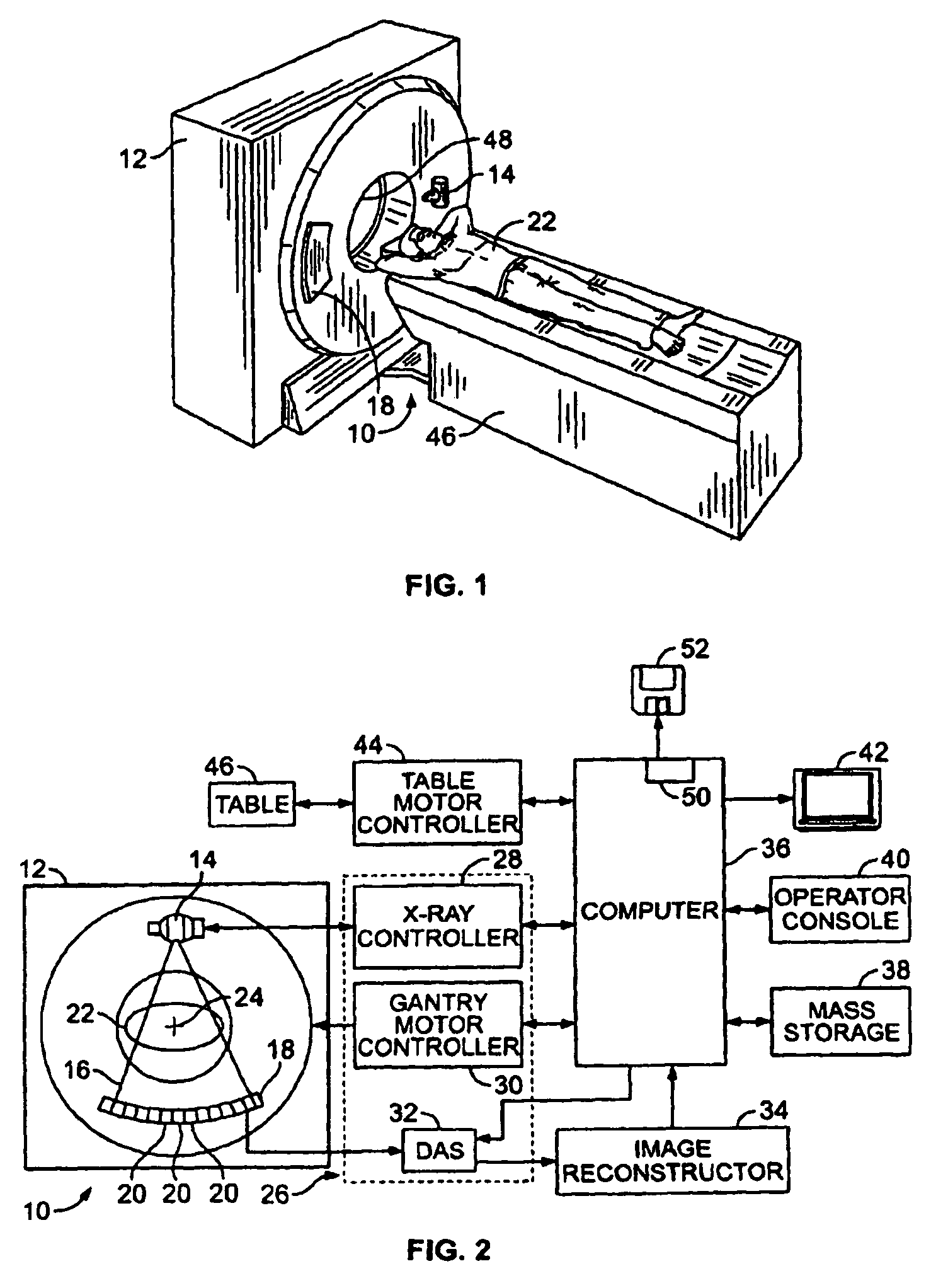
[0017]The foregoing summary, as well as the following detailed description of certain embodiments of the present invention, will be better understood when read in conjunction with the appended drawings. To the extent that the figures illustrate diagrams of the functional blocks of various embodiments, the functional blocks are not necessarily indicative of the division between hardware circuitry. Thus, for example, one or more of the functional blocks (e.g., processors or memories) may be implemented in a single piece of hardware (e.g., a general purpose signal processor or a block of random access memory, hard disk, or the like). Similarly, the programs may be stand alone programs, may be incorporated as subroutines in an operating system, may be functions in an installed software package, and the like. It should be understood that the various embodiments are not limited to the arrangements and instrumentality shown in the drawings, nor are the figures necessarily drawn to scale.

[0...


PUM


Abstract

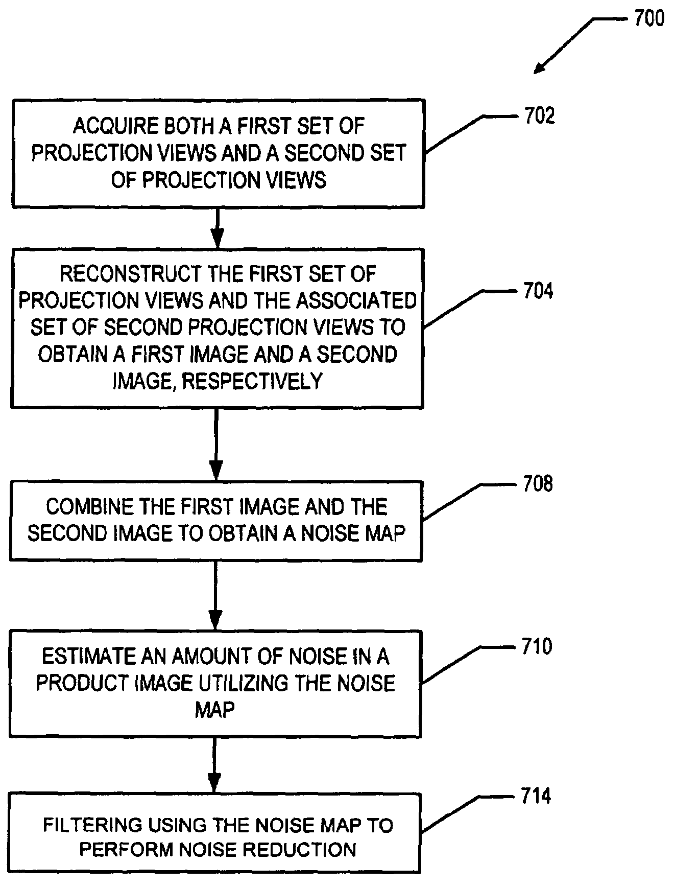
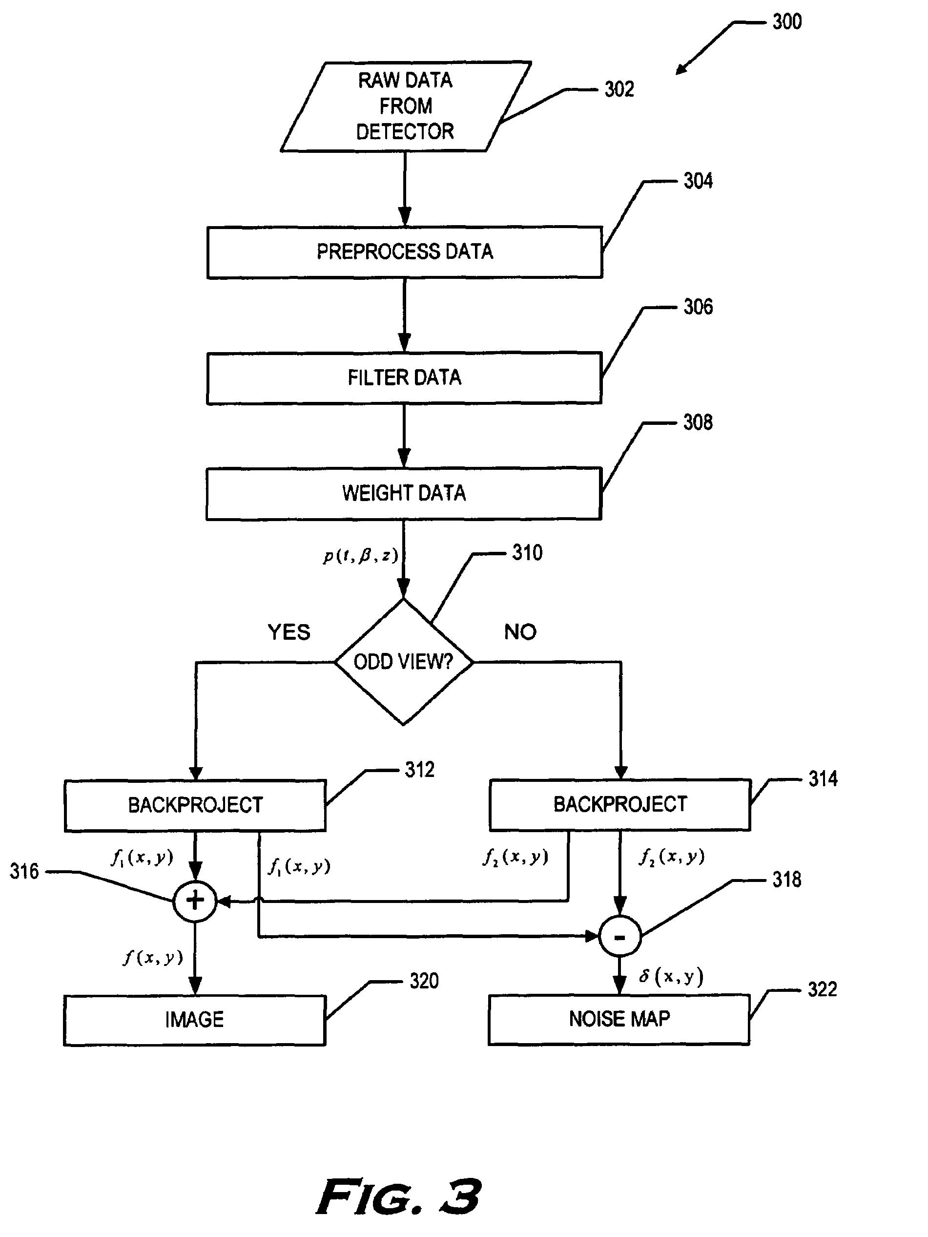
A method for reducing noise in a computed tomographic (CT) image includes acquiring both a first set of projection views and a second set of projection views, wherein for each projection view in the first set of projection views there is an associated projection view in the second set of projection views representing the same object scanned at substantially the same time from substantially the same position. The method further includes reconstructing the first set of projection views and the associated second set of projection views to obtain a first image and a second image, respectively. Next, the first image and the second image are combined to obtain a noise map and an amount of noise in a product image is estimated utilizing the noise map. The method also includes filtering using the noise map to perform noise reduction.

Description

BACKGROUND OF THE INVENTION[0001]This invention relates generally to computed tomographic (CT) imaging, and more particularly to methods and apparatus for noise reduction in CT imaging applications.[0002]Dose reduction has been the focus of research for x-ray CT for many years. By reducing the noise in the reconstructed images, either or both of the x-ray intensity used for scanning or the duration of a scan can be reduced, thereby reducing the dose to a patient while maintaining the same image quality as a scan without the benefit of noise reduction. It is well known that noise reduction can be performed either in projection space or in image space. Speckle reduction methods based on anisotropic diffusion have been proposed to reduce noise, but these methods are computationally intensive and are not able to keep up with the high frame rates of today's scanners.[0003]Improvements of the speckle reductions methods were later proposed as a multi-scale version of anisotropic diffusion....

Claims


Application Information

Patent Timeline
Patent Type & Authority Patents(United States)
IPC IPC(8): A61B6/00
CPCA61B6/032A61B6/482G06T5/002G06T5/20G06T5/50A61B6/405G06T2207/10081G06T2207/30056G06T2200/12A61B6/4021G06T5/70
Inventor HSIEH, JIANGTHIBAULT, JEAN-BAPTISTE
Owner GENERAL ELECTRIC CO
Learn More