Retainer for sleeve for recharging a cleaning, sanitizing or disinfectant fluid spray system

a technology of spray system and refilling sleeve, which is applied in the direction of cleaning process and equipment, packaging, chemical equipment and processes, etc., can solve the problems of requiring shelf space, requiring refill bottle sales, and requiring spillage of refill bottle fluid, so as to facilitate the insertion of the diptube/retainer structure, facilitate the extraction of the sleeve, and stabilize the diptube

Inactive Publication Date: 2010-05-04
KELLY ALBERT R +1
View PDF5 Cites 6 Cited by
  • Summary
  • Abstract
  • Description
  • Claims
  • Application Information

AI Technical Summary

Benefits of technology

[0011]In the present invention, there is presented a recharge sleeve, for use with a spray dispenser device having a container body, a sprayhead mounted with a sealing cap, and an elongated diptube which is inserted into the container body during use, and a retainer applied to the lower (intake) end of the diptube to prevent the sleeve from blocking the lower end of the diptube and to facilitate the extraction of the sleeve from the spray bottle after use, the retainer being adapted to facilitate the insertion of the diptube / retainer structure into the sleeve without the users having to touch the sleeve by hand. The distal or bottommost end of the retainer tapers inwardly for these purposes. The sleeve is comprised of adsorptive material, of one or multiple layers with at least one of the layers being an absorptive material. The absorptive material or the at least one layer thereof in the latter case is impregnated with a non-aqueous chemical composition which will dissolve when contacted with a diluent fluid such as water. The recharge sleeve is formed in an elongated rectangular shape with a center opening for mounting on the diptube. The sleeve material has an outer surface which is porous to fluid filled into the container body so that the fluid can penetrate into the sleeve material and dissolve the chemical composition which has been impregnated therein. A substantially rigid retainer is attached or provided for attachment to the lower end of the diptube for the following benefits. The retainer is used to stabilize the diptube and to keep the sleeve from blocking the intake end of the diptube and impeding or blocking the liquid flow into the diptube during use. The retainer also functions to facilitate the insertion of the diptube into the sleeve and also to facilitate the extraction of the spent sleeve from the spray bottle after use by preventing the wet, heavier and flimsy sleeve from falling off the diptube. The retainer is tapered inwardly at its distal end, i.e., the end on the opposite side of its attachment to the diptube and thereby allows the diptube and the retainer to be slipped easily into the recharge sleeve before use when the sleeve is still in its retail package, so that the treated sleeve can be extracted from the package without having to be touched by the user's hand. Most preferably, the retainer is attached to the lower end of the diptube during manufacture of the diptube. Alternatively, the retainer can be attached either before or after the sleeve is applied to the diptube by the end user.
[0012]In a preferred embodiment, the sleeve material is a multiple layered synthetic, binder-free, nonwoven substrate enclosing an opening along its center axis for inserting the diptube there through. The multiple layers are bonded together without a chemical binder, such as by heat bonding, ultrasonic bonding, stitching, or mechanical or hydraulic entanglement, or are constituted of an open-celled foam material. The cleaning, sanitizing or disinfectant chemical composition is impregnated into the adsorptive material or a layer thereof by coating or spraying the adsorptive material or layer with a treatment solution. The sleeve material has a desired porosity, in order to allow fluid to penetrate through the material and dissolve the chemical composition impregnated therein. The retainer, which is substantially rigid, is preferably made of a polymeric material or a blend thereof, such as polyester or polypropylene and is, preferably, conical in shape. The upper end of the retainer possesses a square-cut shoulder and an inside diameter that can receive the lower (intake) end of the diptube and allow for attachment to the diptube. The inside diameter of the retainer tapers from the upper end of the retainer to the lower end of the retainer so as to accommodate different sized diptubes. The maximum effective outside diameter of the retainer (either that of the retainer's main body or other protruding structures such as ridges) is small enough to allow the unused sleeve to be applied to the diptube without using excessive force and rupturing the sleeve, and yet it is large enough to hold the sleeve in its position and prevent it from slipping downwardly over the diptube during use, so that the sleeve does not block the intake of the diptube during use and for facilitating the spent sleeve being easily extracted from the diptube after use. The square-cut shoulder further helps in retaining the sleeve onto the diptube. The lower end of the retainer has an outside diameter that is significantly smaller than the diameter of the sleeve opening, so that the diptube and the retainer can be easily inserted into the sleeve without requiring the user to touch the sleeve by hand, thereby eliminating the undesired contact between the user's skin and the unused treated sleeve containing highly concentrated and potentially skin sensitizing or irritating treatment compositions. The retainer also possesses at least one side opening at its lower end that allows fluid to flow unobstructed in the event that the lower end of the retainer is in contact with the bottom of the bottle.
[0013]When the spray bottle, with the retainer attached and the sleeve applied, is filled with water, sealed, and shaken, the chemical composition becomes dissolved in the water, thereby creating a cleaning, sanitizing or disinfectant solution that will remain stable and fully active.

Problems solved by technology

One problem is that the refill bottles take up a large volume which incurs additional shipping costs, storage costs, and demand for shelf space.
Another problem is that a refill bottle must be sold for the specific types of fluid it is intended as a refill.
A further problem is that pouring fluid from the refill bottle can incur spills or require potentially hazardous handling of caustic or toxic fluids.
On the other hand, if the fluids must be made in very dilute concentrations for public safety in handling, then the cleaning ability or effectiveness of the product may be compromised.
The refill bottles themselves are discarded after use, thus adding to plastic pollution and landfill waste.
These types of puncturable or burstable cartridge systems are costly to fabricate, complicated to operate, and potentially hazardous if a problem occurs and the user must open the container and reposition or remove a failed cartridge.
However, this type of recharge insert must be purchased with a sharp diptube, and cannot be used with an existing or currently marketed spray dispenser bottle that has a blunt diptube.
Moreover, the sealing walls must be punctured by the user manipulating the diptube while the container is open, thereby presenting a risk that concentrate will be ejected under the pressure applied to the sealing walls back at the user.
This type of design requires the modification of the spray bottles at the point of manufacture and cannot be used economically on the conventional spray bottles.

Method used


Image

  • Retainer for sleeve for recharging a cleaning, sanitizing or disinfectant fluid spray system
  • Retainer for sleeve for recharging a cleaning, sanitizing or disinfectant fluid spray system
  • Retainer for sleeve for recharging a cleaning, sanitizing or disinfectant fluid spray system

Examples


Embodiment Construction

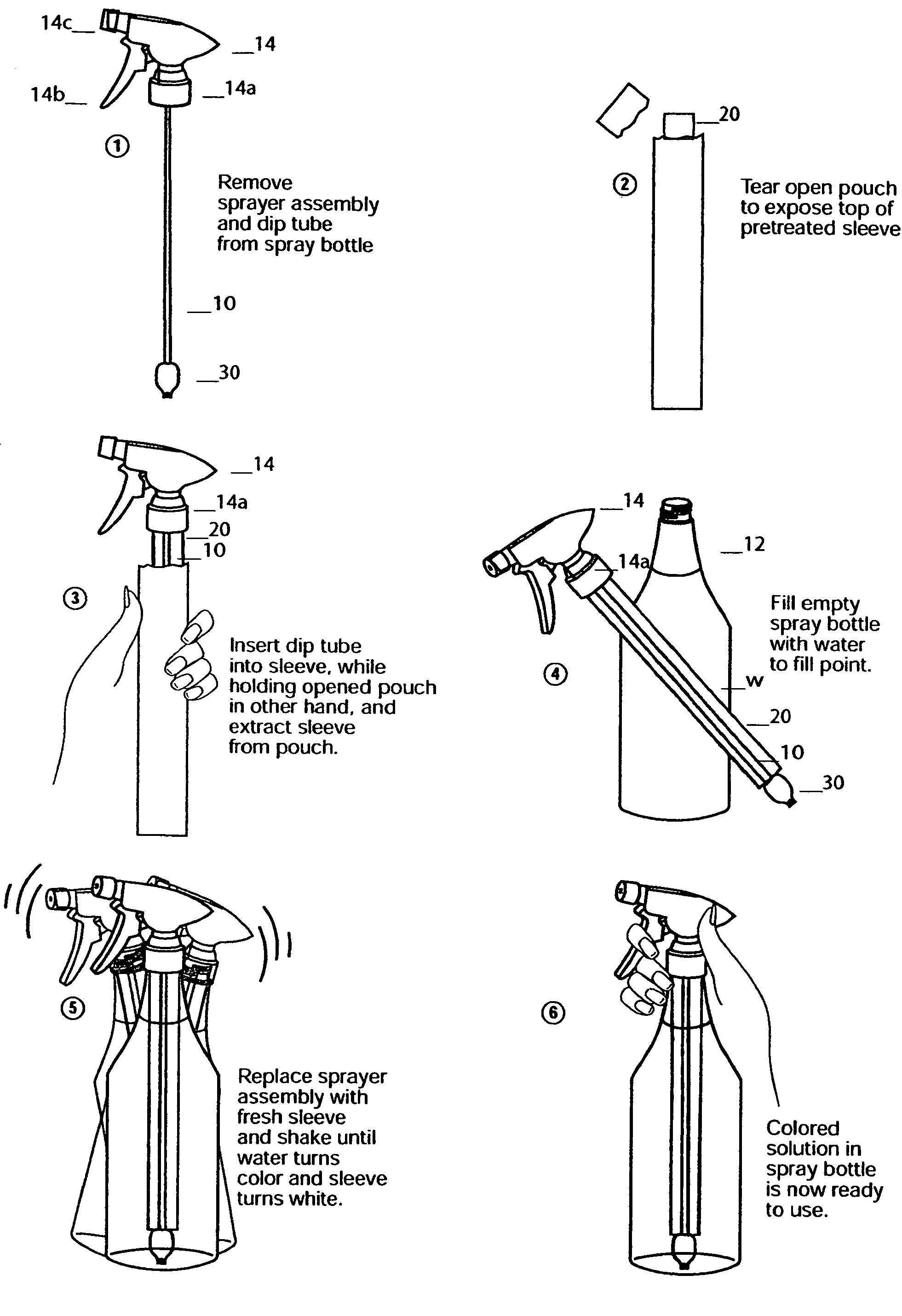
[0019]Referring to FIG. 1, a preferred embodiment of a recharge sleeve 20 in accordance with the present invention is illustrated for use with a standard spray dispenser device having a container body 12 for holding fluid, a sprayhead 14 mounted with a sealing cap 14a, spray trigger 14b, and spray orifice or nozzle 14c, an elongated diptube 10 which is inserted into the body of the container 12 during use, and a retainer 30 attached to the lower end of the diptube during manufacture of the diptube. The recharge sleeve 20 is comprised of an absorbent matrix material with one or multiple layers wherein at least one layer is impregnated with a chemical composition, leaving the sleeve dry-to-the-touch, the chemical composition becoming dissolved in solution with a diluent fluid such as commonly available tap water.

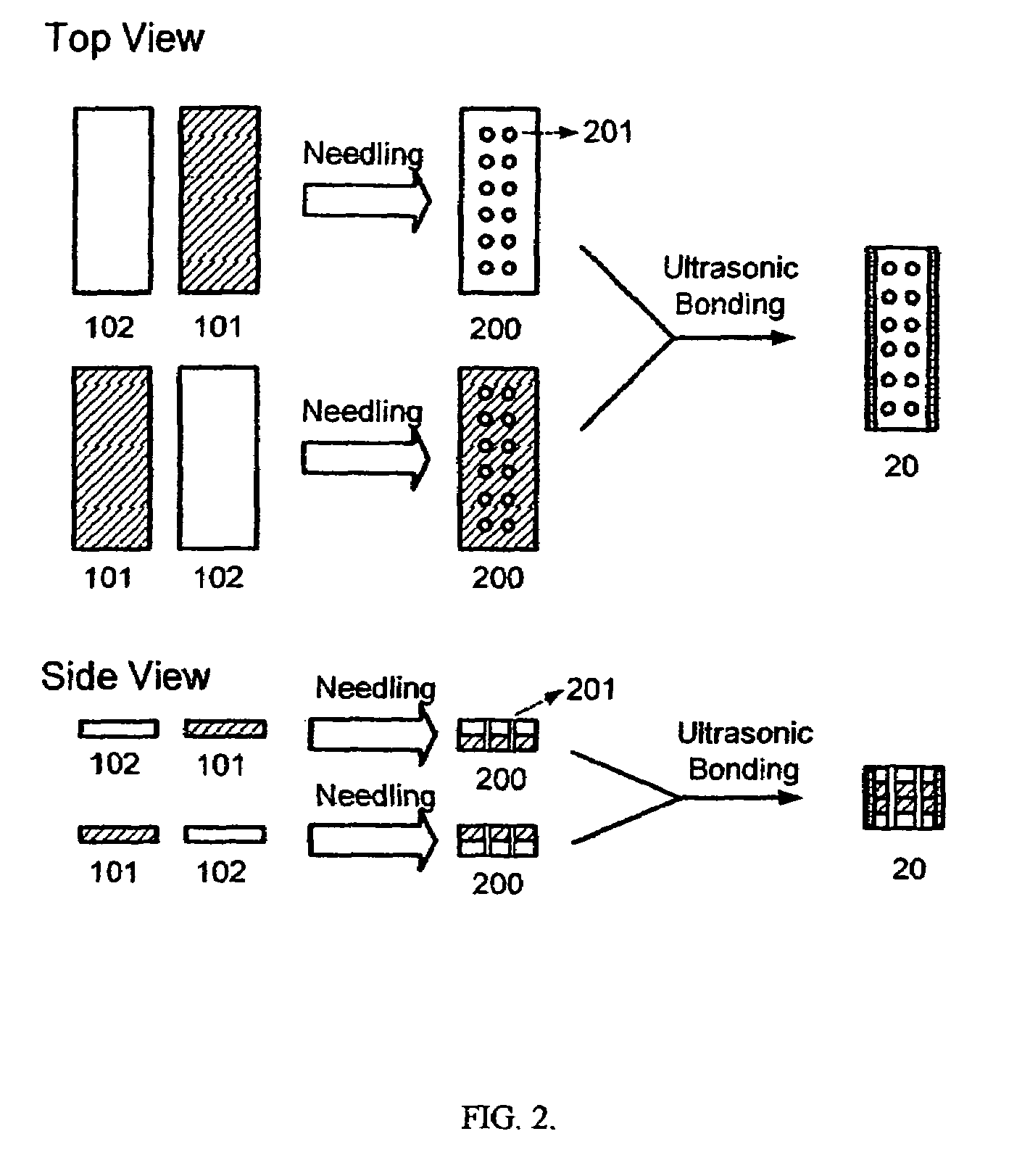
[0020]The recharge sleeve 20 is shaped as a rectangular elongated sleeve by adding or combining at least two layers of water insoluble fibrous material sealed along their elon...


PUM


Abstract

A recharge sleeve for use with a spray dispenser device, made of a matrix comprises an absorptive material impregnated with a chemical composition that dissolves in solution created when the sleeve is contacted with a diluent fluid such as water. The recharge sleeve is elongated in shape with a center opening parallel to the long edges of the sleeve for mounting on the diptube of the spray dispenser device. A conically shaped retainer formed of rigid plastic is attached or provided for attachment to the lower end of the diptube for stabilizing the diptube and retaining the recharge sleeve clear of the bottom of the retainer after the sleeve has been applied to the diptube. When of the spray dispenser device is sealed and the spray dispenser device is shaken, the fluid penetrates into the matrix material, and the chemical composition dissolves in the fluid creating a cleaning, sanitizing, or disinfectant solution that will remain stable and fully active in use.

Description

RELATED APPLICATION[0001]This application is a continuation in part of U.S. application Ser. No. 10 / 934,960 entitled Sleeve For Recharging A Cleaning, Sanitizing Or Disinfectant Fluid Spray System filed Sep. 7, 2004 now abandoned.FIELD OF THE INVENTION[0002]This invention generally relates to spray bottle systems for dispensing cleaning, sanitizing or disinfectant fluids, and more particularly, to a recharge sleeve for placement over the diptube provided with a position-fixing retainer mounted on the bottom-most portion of the diptube for holding the sleeve clear of the lower intake end of the diptube and for facilitating the extraction of the sleeve from the spray bottle after use, the retainer also being adapted for facilitating the manual insertion of the diptube / retainer structure into the sleeve without requiring the user to touch the sleeve by hand.BACKGROUND OF THE INVENTION[0003]Due to regulations curtailing the use of aerosol dispensers for chemical reagents that discharge ...

Claims


Application Information

Patent Timeline
Patent Type & Authority Patents(United States)
IPC IPC(8): B67D7/58
CPCB05B11/0081B05B11/3057B05B11/1057
Inventor KELLY, ALBERT R.SCHMIDT, GEORGE
Owner KELLY ALBERT R
Why Eureka
Try Eureka