Hydrocarbon emission scavenger

a technology of hydrocarbons and scavengers, applied in the field of compositions, can solve problems such as reducing the efficiency of engines, and achieve the effects of reducing engine efficiency, effective absorption of hydrocarbons, and increasing the resistance of the intake system

Inactive Publication Date: 2010-05-04
MULTISORB TECH INC
View PDF18 Cites 18 Cited by
  • Summary
  • Abstract
  • Description
  • Claims
  • Application Information

AI Technical Summary

Benefits of technology

[0012]A hydrocarbon reduction system designed to be located within an engine component exposed to unburned fuel vapors preferably is at least somewhat flexible or compliant. This allows the component to conform easily to an irregular inside surface of the engine component in which it is located. An effective hydrocarbon reduction system must have a relatively high capacity for adsorbing hydrocarbon molecules relative to its size. A high effective surface area is an advantage as this improves the surface area to air flow ratio.
[0014]The present invention provides a structure that provides maximum adsorptive capacity in a structure that binds the sorbent in a relatively compliant, porous structure. The compliant nature of the structure allows it to be readily inserted into close quarters. The porosity of the structure not only allows the adsorption of hydrocarbon molecules, but also allows desorption of hydrocarbon very efficiently with virtually no loss in capacity over repeated cycles of use.
[0016]The present invention provides porous structure that permits a large surface area for exposure of the adsorbent and therefore an improved rate and efficiency of adsorption and desorption. The structure has an improved adsorption capacity per unit volume and therefore lends itself to size reduction with out compromising performance criteria that are requirements for insertion into the intake system of an engine. The flexibility of the porous structure permits it to conform to an irregular shaped air intake passage and the structure can be molded which lends to simple, clean and low cost designs.

Problems solved by technology

For example, when used in the intake system of the engine the sorbent structure must not significantly increase the resistance of the intake system to the passage of air, as this would reduce the efficiency of the engine.

Method used


Image

  • Hydrocarbon emission scavenger
  • Hydrocarbon emission scavenger
  • Hydrocarbon emission scavenger

Examples


Embodiment Construction

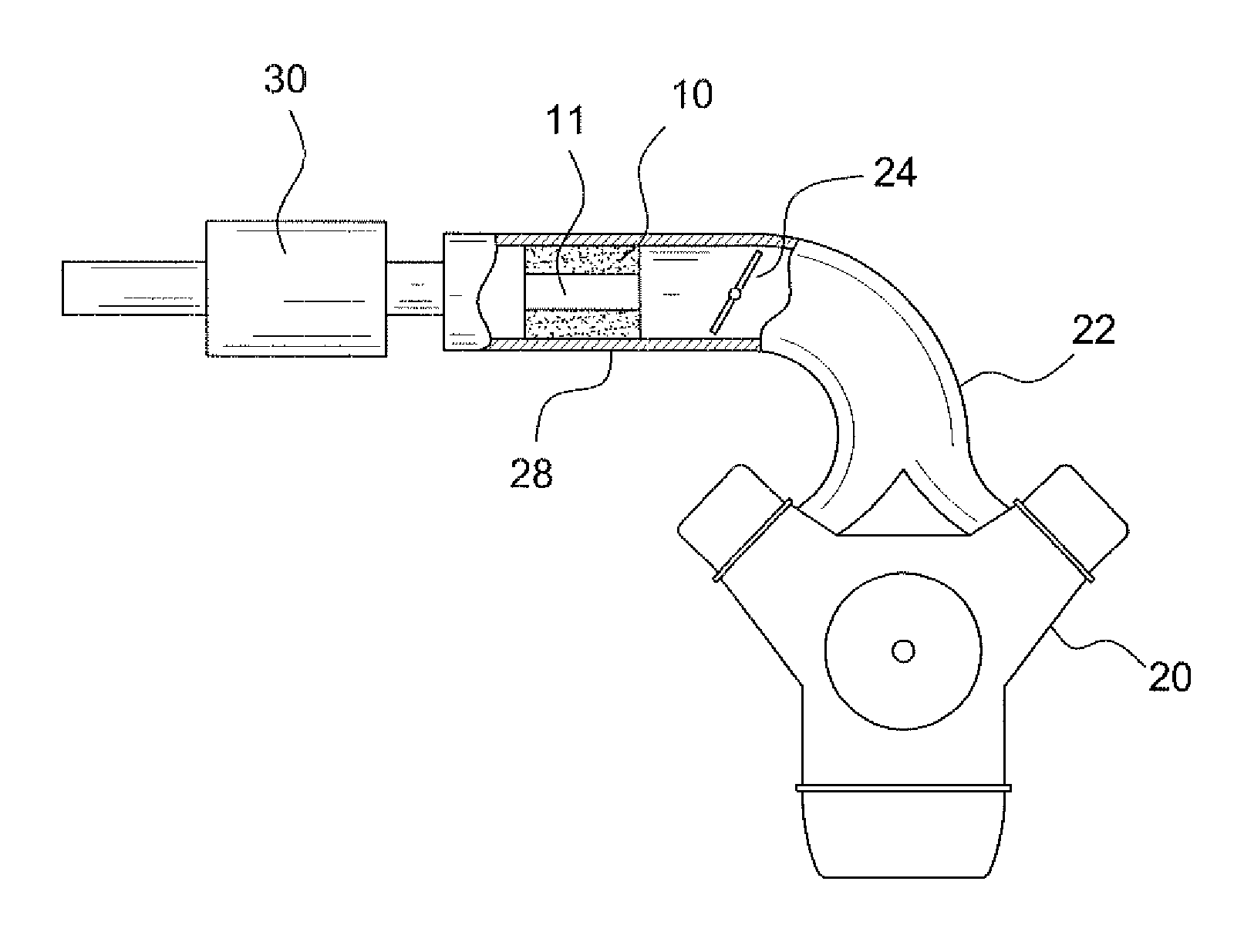
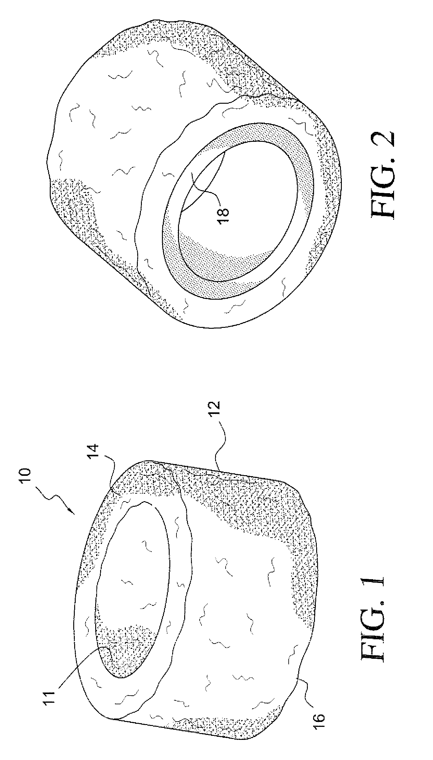
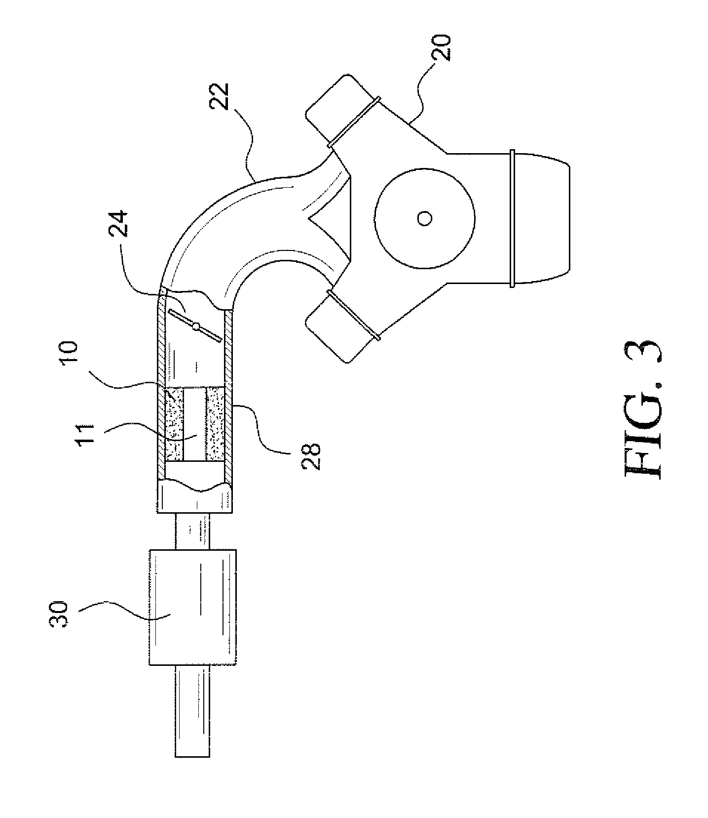
[0025]Referring to the drawings, FIG. 1 shows a hydrocarbon adsorbing structure of the present invention generally indicated at 10. The structure generally is a tubular body formed by sintering a mixture of the hydrocarbon adsorbent and a resin binder. While the tubular body defines a central opening 11 for the passage of air, it should be appreciated that the tubular body is porous in that air or other vapors can flow radially through the tubular wall 12 of the body and longitudinally through the body from one face 14 to the other 16.

[0026]In some cases the tubular body 10 may exhibit loss of adsorbent material from its surfaces in the form of dust. To minimize such loss, particularly in the environment of an engine air intake, FIG. 2 shows the tubular body of FIG. 1 provided with a porous liner 18. The liner preferably is formed of the same sintered resin but is adsorbent material-free so no hydrocarbon is adsorbed by the liner as vapors flow in a tortuous path through the liner.

[...


PUM

PropertyMeasurementUnit
sizeaaaaaaaaaa
particle sizeaaaaaaaaaa
temperaturesaaaaaaaaaa

Abstract

A hydrocarbon adsorber and a thermoplastic resin combined and formed to a porous scavenger for insertion into the air intake system of a motor vehicle engine. The resulting porous scavenger adsorbs volatile hydrocarbon molecules from raw fuel remaining in the air intake when the engine is shut off. The adsorbed molecules are then stripped or purged from the scavenger and reintroduced into the air intake when the engine is next started.

Description

CROSS-REFERENCE TO RELATED APPLICATIONS[0001]NoneSTATEMENT REGARDING FEDERALLY SPONSORED RESEARCH OR DEVELOPMENT[0002]NoneREFERENCE TO A “SEQUENCE LISTING”[0003]Not applicable.BACKGROUND OF THE INVENTION[0004]1. Field of the Invention[0005]This invention relates generally to compositions for adsorbing hydrocarbon molecules that have vaporized and more particularly to compositions and structures useful in hydrocarbon-fueled engines such as generators, motor vehicles and similar applications for scavenging hydrocarbon molecules from raw fuel that may be present in one or more systems of the engine including but not limited to the air intake system.[0006]2. Description of Related Art[0007]As automotive emission requirements have become much more stringent, the emission of hydrocarbons from sources other than the fuel tank and the exhaust of motor vehicles is subject to increasing federal regulation. Significant levels of hydrocarbon emission may come from such diverse sources as vehicl...

Claims


Application Information

Patent Timeline
Patent Type & Authority Patents(United States)
IPC IPC(8): B01D53/04F02M33/02
CPCB01D53/02F02M35/046B01J20/103B01J20/18B01J20/20B01J20/261B01J20/28004B01J20/2803B01J20/28042B01J20/28085B01J20/30B01J20/3007F02M25/08F02M35/10019F02M35/10144F02M35/10321F02M35/0218B01D2253/202B01D2257/702B01D2257/7022B01D2257/708B01D2259/4516B01J2220/46B01J2220/66B01D2253/102
Inventor HURLEY, THOMAS J.INCORVIA, SAMUEL A.
Owner MULTISORB TECH INC
Why Eureka
Try Eureka