Eureka AIR delivers breakthrough ideas for toughest innovation challenges, trusted by R&D personnel around the world.

Chemical liquid supply apparatus and a chemical liquid supply method

Inactive Publication Date: 2010-05-04
KOGANEI
View PDF112 Cites 13 Cited by
  • Summary
  • Abstract
  • Description
  • Claims
  • Application Information

AI Technical Summary

Benefits of technology

[0008]Thus, a conventional method, in which the bubbles are removed through the filter and exhausted from the filter, has its limitations. To solve the problems as described above, it is necessary, even at a place or places other than the filter in the supply apparatus, to properly remove the bubbles included in the chemical liquid and exhaust them outside the supply apparatus.

Problems solved by technology

If bubbles are mixed into the apparatus in discharging the chemical liquid such as a photoresist liquid, the bubbles absorb a pressure trying to push out the chemical liquid and thereby a discharge amount of chemical liquid becomes unstable and accuracy of the discharge is reduced.
Due to this, a semiconductor integrated circuit to be formed onto the semiconductor wafer has been difficult to manufacture with high quality and good yield.
However, since the bubbles gradually adhere to the surface of the filter and the clogging thereof occurs, the capability of capturing the bubbles is reduced gradually.
Due to this, the filter cannot completely capture the bubbles in the chemical liquid, and the chemical liquid containing the bubbles is often discharged on the surface of the semiconductor wafer.
Consequently, it has been difficult to improve the yield of manufacturing the semiconductor integrated circuit.
Thus, a conventional method, in which the bubbles are removed through the filter and exhausted from the filter, has its limitations.

Method used


Image

  • Chemical liquid supply apparatus and a chemical liquid supply method
  • Chemical liquid supply apparatus and a chemical liquid supply method
  • Chemical liquid supply apparatus and a chemical liquid supply method

Examples


Embodiment Construction

[0018]In the following, an embodiment of the present invention will be in detail explained based on the drawings.

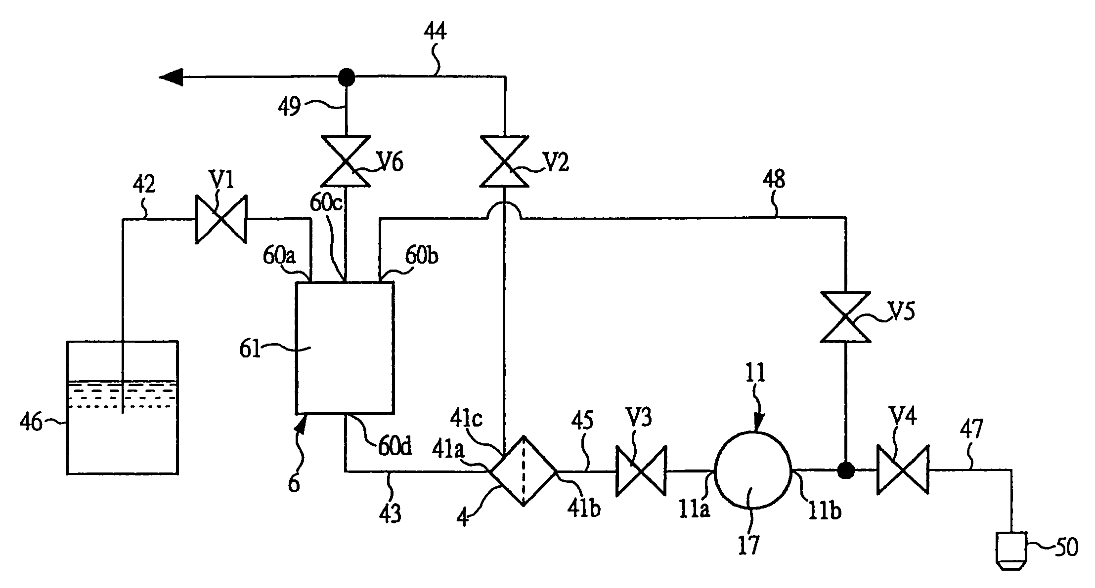
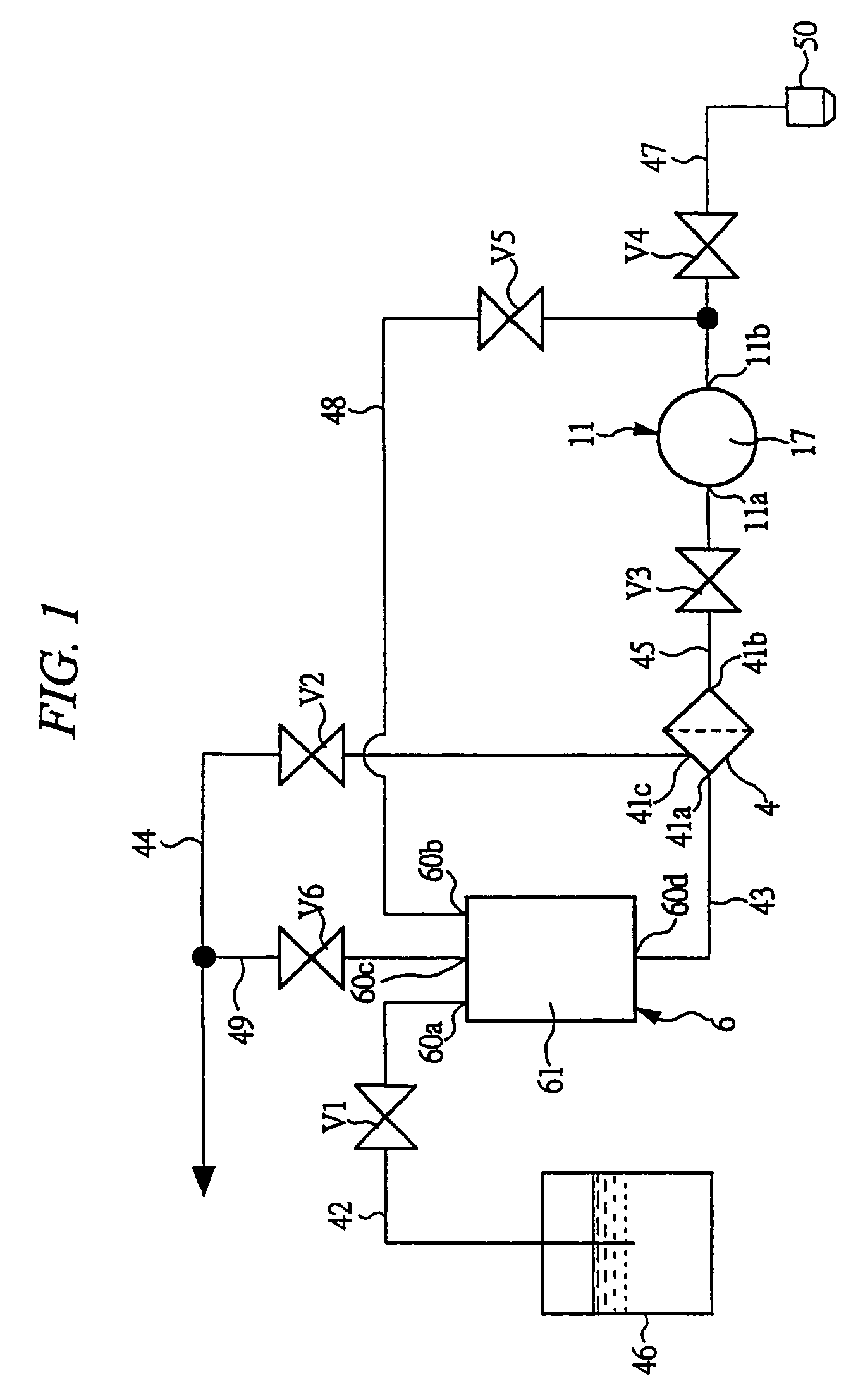
[0019]FIG. 1 is a liquid circuit diagram schematically showing a chemical liquid supply apparatus that is an embodiment of the present invention. As shown in FIG. 1, a buffer tank section 6 of the chemical liquid supply apparatus is inside provided with a liquid accumulation chamber 61. On a ceiling wall of the buffer tank section, there are formed: a liquid inpour port 60a to which a liquid introduction flow path 42 is connected; a liquid inpour port 60b to which a return flow path 48 is connected; and an exhaust port 60c to which an exhaust flow path 49 is connected. On a bottom wall of it, there is formed a liquid discharge vent 60d to which a communication path 43 is connected.

[0020]To the liquid inpour port 60a of the buffer tank section 6, one end of the liquid introduction flow path 42, provided with an introduction valve V1 for opening / closing the flow path, is co...


PUM

PropertyMeasurementUnit
Timeaaaaaaaaaa
Flow rateaaaaaaaaaa

Abstract

A buffer tank section (6) includes a liquid accumulation chamber (61) communicating with, through a liquid introduction flow path (42), a liquid tank (46) accumulation chemical liquid. A filter section (4) includes a filter inlet (41a) and a filter outlet (41b), wherein the filter inlet (41a) communicates with a liquid discharge vent (60d) of the buffer tank section (6). In a pump (11), a pump inlet (11a) is connected to the filter outlet (41b) and a pump outlet (11b) is connected to a discharge nozzle (50) through a liquid discharge flow path (47). A return flow path (48) is connected between the pump outlet (11b) and the buffer tank section (6), wherein the chemical liquid, discharged from the pump (11), is returned to the liquid accumulation chamber (61). An exhaust flow path (49) is connected to the buffer tank section (6), thereby exhausting air in the liquid accumulation chamber (61).

Description

CROSS REFERENCE TO PRIOR APPLICATIONS[0001]Applicant hereby claims foreign priority under 35 U.S.C. § 119 from JAPANESE Patent Application No. 2001-401216 filed 28 Dec. 2001 and PCT International Application No. PCT / JP02 / 12823 filed 6 Dec. 2002 the disclosures of which are herein incorporated by reference.TECHNICAL FIELD OF THE INVENTION[0002]The present invention relates to a chemical liquid supply apparatus and a chemical liquid supply method, which discharge a predetermined amount of liquid such as a chemical liquid or the like, and which is preferably used to, for example, coat a photoresist liquid onto the surface of a semiconductor wafer.BACKGROUND OF THE INVENTION[0003]A chemical liquid, such as a photoresist liquid, spin on glass liquid, polyimide resin liquid, pure water, etching liquid, organic solvent, and the like, has been used in manufacturing processes in various technical fields such as techniques of manufacturing a liquid crystal board, a magnetic disk, a multi-laye...

Claims


Application Information

Patent Timeline
IPC IPC(8): B01D35/01F04B23/02B01D19/00B05C11/10F04B53/06G03F7/16H01L21/00H01L21/027
CPCB01D19/0068H01L21/6715G03F7/16H01L21/027
Inventor YAJIMA, TAKEO
Owner KOGANEI
Why Eureka
Eureka Blog
Learn More