
Systems and methods for monitoring and controlling the operation of extreme ultraviolet (EUV) light sources used in semiconductor fabrication

a technology of extreme ultraviolet light source and system, applied in the field of semiconductor fabrication, can solve the problems of reducing the overall productivity, difficult to monitor the performance of these sources, and system quickly losing their reflectivity

Inactive Publication Date: 2010-05-04
FREESCALE SEMICON INC +2
View PDF10 Cites 5 Cited by
  • Summary
  • Abstract
  • Description
  • Claims
  • Application Information

AI Technical Summary

Benefits of technology

This approach enables efficient monitoring and control of EUV sources without the need for high vacuum conditions, reducing costs and increasing productivity by utilizing available metrology equipment and extending system lifetime.

Problems solved by technology

It is, however, very difficult to monitor the performance of these sources.
First, multi-layer mirrors used in these systems quickly lose their reflectivity over time and frequently need to undergo expensive and time consuming calibration procedures, thus decreasing the overall productivity.
Moreover, existing EUV systems must perform measurements in a high vacuum, which further adds to the cost and complexity of the system.
The shortcomings mentioned above are not intended to be exhaustive, but rather are among many that tend to impair the effectiveness of previously known techniques for monitoring energy from EUV sources.
The problems listed above are sufficient to demonstrate that the methodologies appearing in the art have not been satisfactory, and that a significant need exists for the systems and methods described and claimed herein.

Method used


Image

  • Systems and methods for monitoring and controlling the operation of extreme ultraviolet (EUV) light sources used in semiconductor fabrication
  • Systems and methods for monitoring and controlling the operation of extreme ultraviolet (EUV) light sources used in semiconductor fabrication
  • Systems and methods for monitoring and controlling the operation of extreme ultraviolet (EUV) light sources used in semiconductor fabrication

Examples


Embodiment Construction

[0020]In the following detailed description, reference is made to the accompanying drawings that illustrate embodiments of the present invention. These embodiments are described in sufficient detail to enable a person of ordinary skill in the art to practice the invention without undue experimentation. It should be understood, however, that the embodiments and examples described herein are given by way of illustration only, and not by way of limitation. Various substitutions, modifications, additions, and rearrangements may be made without departing from the spirit of the present invention. Therefore, the description that follows is not to be taken in a limited sense, and the scope of the present invention is defined only by the appended claims.

[0021]The present invention provides systems and methods for monitoring and controlling the operation of EUV sources used in semiconductor fabrication. Typical EUV sources operate by application of a large electrical field and / or high-energy ...


PUM


Abstract

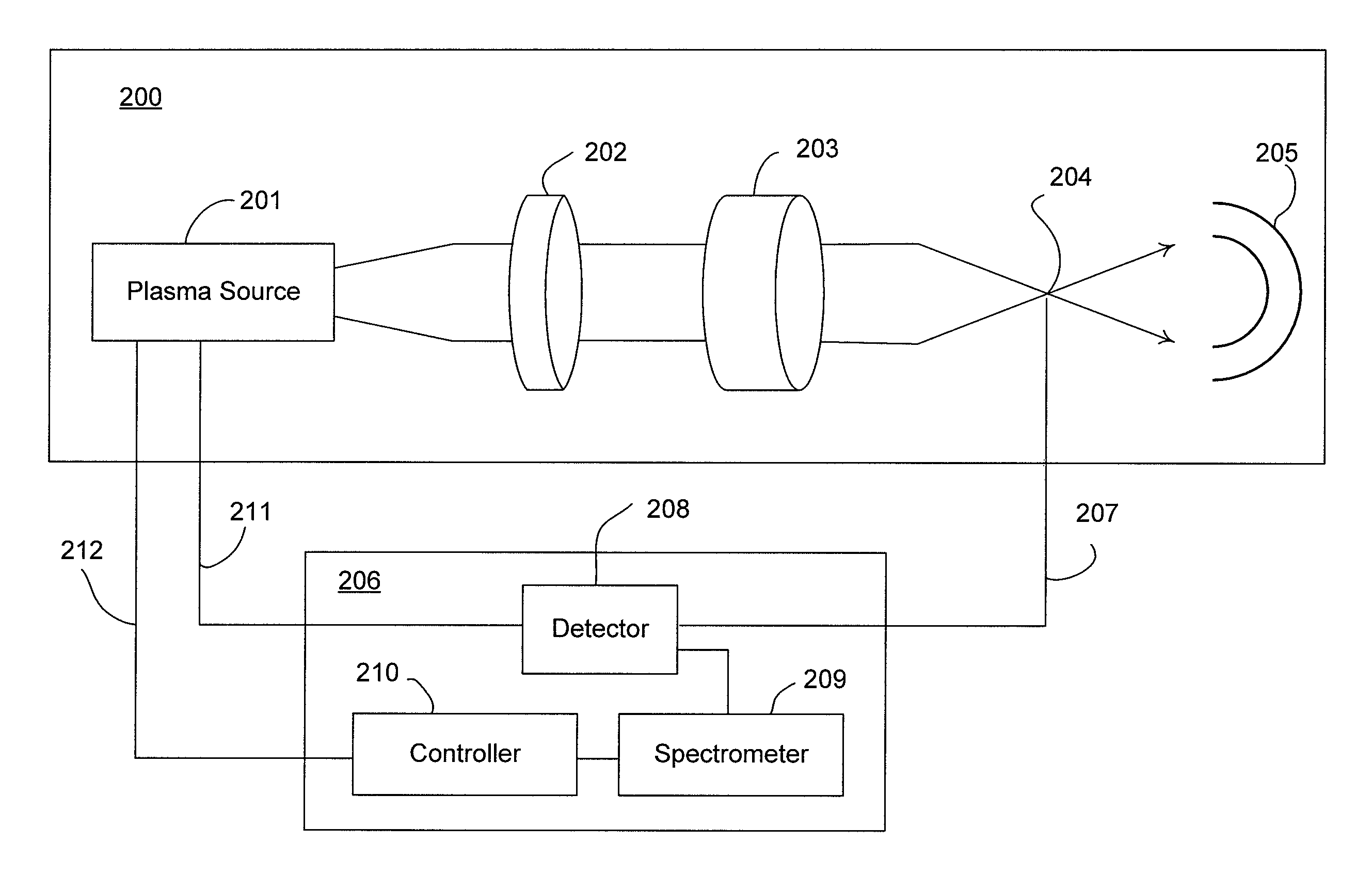
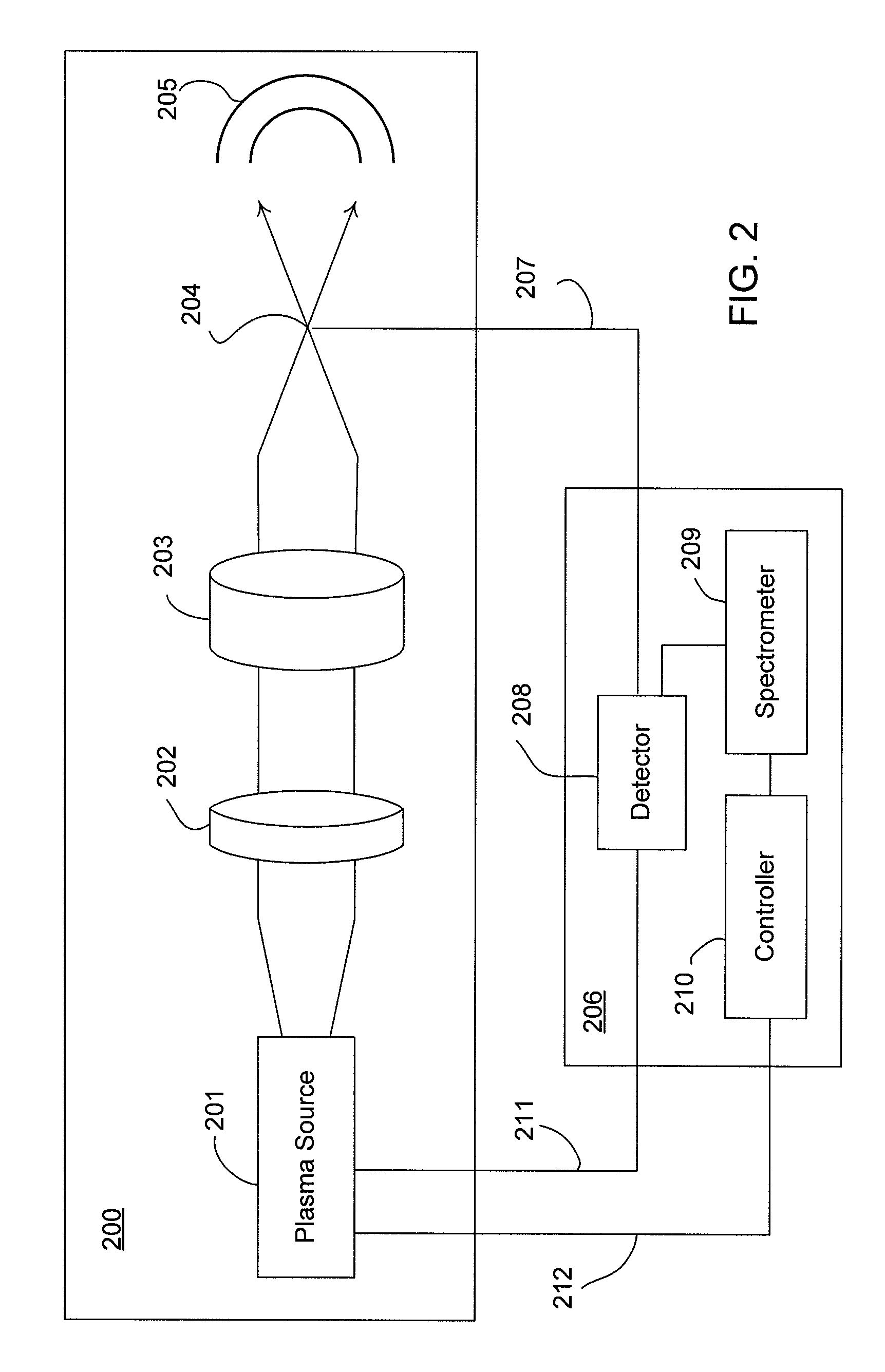
Systems and methods for monitoring and controlling the operation of extreme ultraviolet (EUV) sources used in semiconductor fabrication are disclosed. A method comprises providing a semiconductor fabrication apparatus having a light source that emits in-band and out-of-band radiation, taking a first out-of-band radiation measurement, taking a second out-of-band radiation measurement, and controlling the in-band radiation of the light source, at least in part, based upon a comparison of the first and second out-of-band measurements. An apparatus comprises a detector operable to detect out-of-band EUV radiation emitted by an EUV plasma source, a spectrometer coupled to the electromagnetic detector and operable to measure at least one out-of-band radiation parameter based upon the detected out-of-band EUV radiation, and a controller coupled to the spectrometer and operable to monitor and control the operation of the EUV plasma source based upon the out-of-band measurements.

Description

BACKGROUND OF THE INVENTION[0001]1. Field of the Invention[0002]The present invention relates to semiconductor fabrication, and more particularly to systems and methods for monitoring and controlling the operation of extreme ultraviolet (EUV) light sources used in semiconductor fabrication.[0003]2. Description of Related Art[0004]Semiconductor fabrication typically involves dozens, or even hundreds of individual operations. In general terms, these operations can be classified as: layering, patterning, doping, and heat treatments. Among these, patterning (also referred to as “lithography”) is considered to be the most critical operation because it sets the physical dimensions of the resulting devices on the semiconductor wafer.[0005]Patterning comprises a series of steps by which selected portions of material deposited on the wafer surface are removed, thus leaving a “pattern” thereon. The sequence of steps may be described as follows. First, a pattern is formed on a photomask or ret...

Claims


Application Information

Patent Timeline
Patent Type & Authority Patents(United States)
IPC IPC(8): G21K5/00
CPCH05G2/003
Inventor BAKSHI, VIVEKWURM, STEFANKEMP, KEVIN
Owner FREESCALE SEMICON INC
Learn More