Low-profile broadband filter antenna

A technology of filter antenna and microstrip antenna, which is applied in the field of LTE wireless communication system and low-profile broadband filter antenna, can solve the problems of narrow working frequency band, high profile and large size of directional filter microstrip antenna, and achieve miniaturization and reduction Sectional, reduced surface area effects

Active Publication Date: 2019-03-08
XIDIAN UNIV +1
View PDF14 Cites 3 Cited by
  • Summary
  • Abstract
  • Description
  • Claims
  • Application Information

AI Technical Summary

Problems solved by technology

[0007] The purpose of the present invention is to overcome the deficiencies in the above-mentioned prior art, and propose a low-profile broadband filter antenna, w

Method used


Image

  • Low-profile broadband filter antenna
  • Low-profile broadband filter antenna
  • Low-profile broadband filter antenna

Examples


Embodiment 1

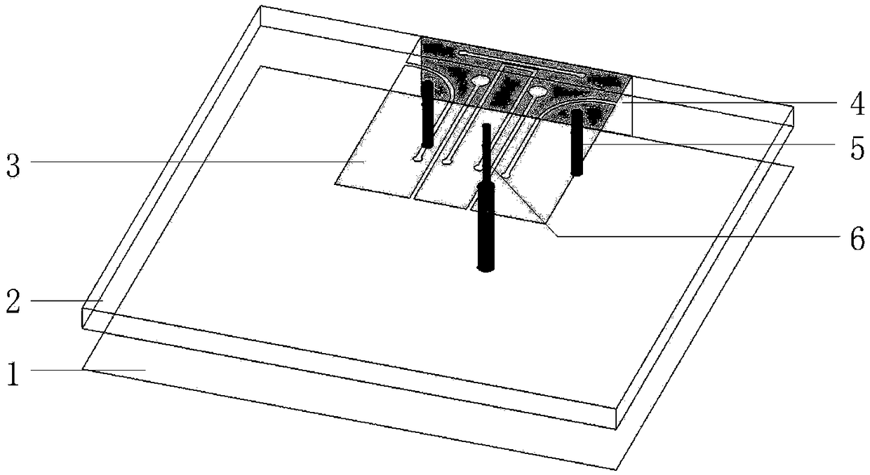
[0026] refer to figure 1 , refer to figure 2 and image 3

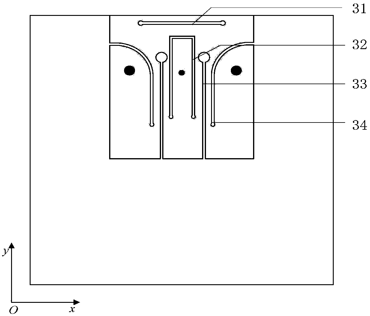
[0027] A low-profile broadband filter antenna, including a metal floor 1, a dielectric plate 2 arranged directly above the metal floor 1, a rectangular metal patch 3 located at the edge of the upper surface of the dielectric plate 2, a rectangular metal wall 4 on the side, and a Two metal short-circuit posts 5 and coaxial probes 6 of the board 2; one end of the rectangular metal wall 4 is connected to the edge of the rectangular metal patch 3, and the other end extends to the edge of the metal floor 1, and it is characterized in that the The first slit 31 with both ends of the closed structure is etched on one side of the edge of the rectangular metal patch 3 connected to the rectangular metal wall 4, and the central part of the rectangular metal patch 3 is etched with an opening facing the other side. U-shaped slit 32, the two sides of the U-shaped slit 32 are respectively etched with the same second slit 33, one...

Embodiment 2

[0035] The structure of embodiment 2 is the same as that of embodiment 1, only the following parameters have been adjusted:

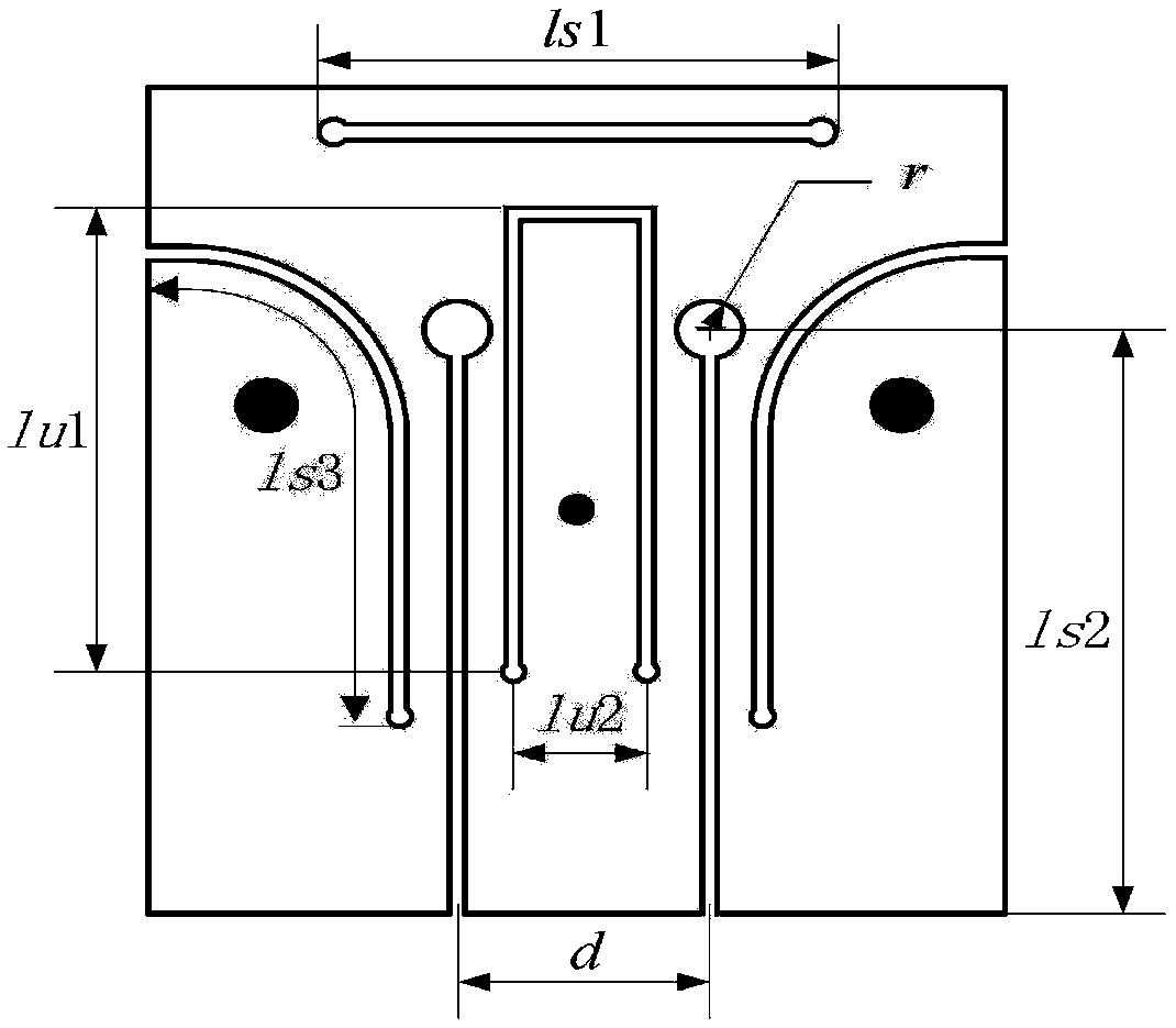
[0036] The two arms of the U-shaped slit 32 are parallel to each other, the length of the two arms of the U-shaped slit 32 is lu1, and the distance between them is lu2, wherein lu1=13.5mm, lu2=2mm.

[0037] The second slits are parallel to each other, the length of the second slits is ls2, and the distance is d, wherein, ls2=16mm, d=4mm.

[0038] The straight segments of the third slit 34 are parallel to each other, and the total length of the third slit 34 is ls3, wherein ls3=14.5mm.

[0039] The length of the first slit 31 is ls1, wherein ls1=10mm.

Embodiment 3

[0041] The structure of embodiment 3 is the same as that of embodiment 1, only the following parameters have been adjusted:

[0042] The two arms of the U-shaped slit 32 are parallel to each other, the length of the two arms of the U-shaped slit 32 is lu1, and the distance between them is lu2, wherein lu1=19.5mm, lu2=6mm.

[0043] The second slits are parallel to each other, the length of the second slits is ls2, and the distance is d, wherein, ls2=24mm, d=8mm.

[0044] The straight segments of the third slit 34 are parallel to each other, and the total length of the third slit 34 is ls3, wherein ls3=21.5mm.

[0045] The length of the first slit 31 is ls1, wherein ls1=14mm.

[0046] Below in conjunction with simulation experiment, technical effect of the present invention is described further:

[0047] 1. Simulation conditions and content:

[0048] The low-profile broadband filter antenna described in Embodiment 1 is placed on the xoy plane, and the above-mentioned Embodime...


PUM


Abstract

The invention proposes a low-profile broadband filter antenna. The low-profile broadband filter antenna is used for solving the problems of narrow broadband, high profile and large size of the prior art. The low-profile broadband filter antenna comprises a metal floor, a dielectric late, a rectangular metal patch, a rectangular metal wall, two metal short-circuit posts and a coaxial probe, whereinthe dielectric plate is arranged right above the metal floor, the rectangular metal patch is arranged at an edge of an upper surface of the dielectric plate, the rectangular metal wall is arranged ata side surface, the two metal short-circuit posts penetrate through the dielectric plate, first gap is etched in an edge where the rectangular metal patch and the rectangular metal wall are connected, two ends of the first gap are of enclosed structures, a U-shaped gap is etched in a central part of the rectangular patch, an opening of the U-shaped gap faces the other side, same second gaps are etched in two sides of the U-shaped gap, one end of each second gap is opened, the other end of the second gap is of an enclosed structure, and same third gaps are etched in two sides of the second gap. The low-profile broadband filter antenna has the broadband characteristic, the relative bandwidth reaches 25.3%, the out-of-band radiation of the antenna is suppressed, and the frequency selectivityof the antenna is improved.

Description

technical field [0001] The invention relates to the technical field of filter antennas, in particular to a low-profile broadband filter antenna, which can be used in LTE wireless communication systems. Background technique [0002] With the rapid development of communication technology, devices in communication systems tend to be integrated, multi-functional, and high-performance, and the same is true in the RF front-end. Antennas and filters are important circuit components of the RF front-end. Their performance and size determine the performance of the system. Therefore, it is necessary to integrate the antenna and bandpass filter to improve the integration of the RF front-end. The traditional solution is to directly cascade the filter network and the antenna to achieve filtering. The defect of this design method is that it introduces a certain insertion loss and leads to impedance mismatch to a certain extent. [0003] In recent years, some integrated designs of filters ...

Claims


Application Information

Patent Timeline
IPC IPC(8): H01Q1/38H01Q1/48H01Q1/50H01Q9/04
CPCH01Q1/38H01Q1/48H01Q1/50H01Q9/0407
Inventor 姜文赵一凡洪涛龚书喜
Owner XIDIAN UNIV
Why Eureka
Try Eureka