Light emitting diode having plurality of light emitting cells and method of fabricating the same

a light emitting diode and light emitting cell technology, applied in the field of light emitting diodes, can solve the problems of wire deterioration, wire disconnection, and increase in wiring resistance, so as to prevent wire disconnection, increase in wire resistance, or performance deterioration of light emitting cells

Active Publication Date: 2010-05-04
SEOUL SEMICONDUCTOR
View PDF22 Cites 73 Cited by
  • Summary
  • Abstract
  • Description
  • Claims
  • Application Information

AI Technical Summary

Benefits of technology

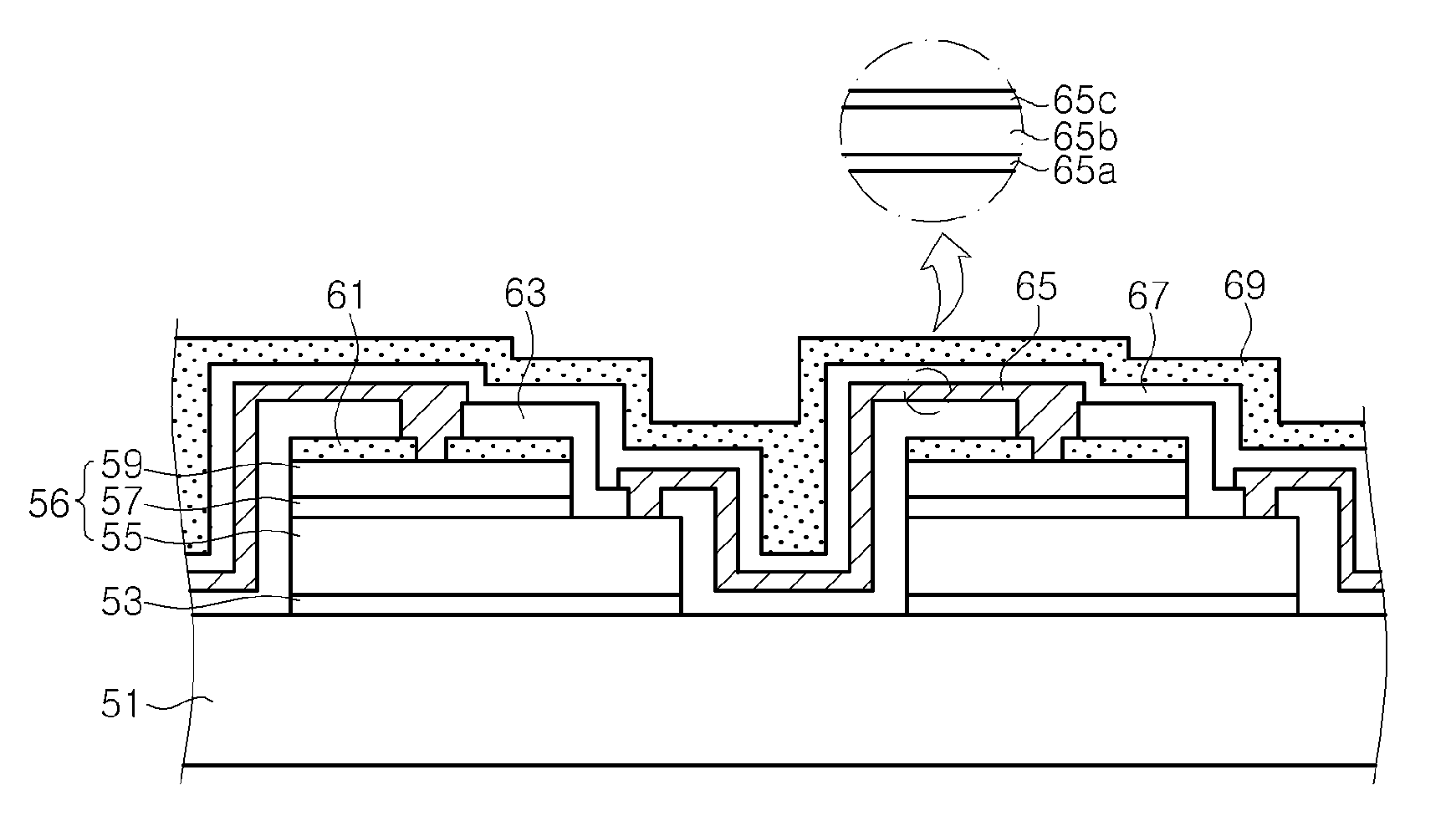
[0012]The present invention provides a light emitting diode that may prevent disconnection of wires, increase in wire resistance, or performance deterioration of light emitting cells caused by moisture intrusion or external impact, and a method of fabricating the same.

Problems solved by technology

However, an interconnection between the light emitting cells via the air-bridge wires may cause the wires to deteriorate, that is, problems such as disconnection of the wires or increase in wiring resistance due to moisture or impact from the outside.
However, the wires formed by the step-cover process may be exposed to the outside and may also be disconnected by moisture or external impact.
Furthermore, since a number of wires are used in the light emitting diode, moisture may intrude into the light emitting cells along the wires, thereby deteriorating luminescent efficiency of the light emitting cells.
For such a white light emitting diode, a color-conversion material layer containing the fluorescent materials may be formed during a packaging process, which is independent of a process of fabricating the light emitting diode chip, so that the packaging process may become complicated, thereby causing a high failure rate in the packaging process.
Failures that occur during the packaging process may be is more expensive than those that occur during the process of fabricating the light emitting diode chip.

Method used


Image

  • Light emitting diode having plurality of light emitting cells and method of fabricating the same
  • Light emitting diode having plurality of light emitting cells and method of fabricating the same
  • Light emitting diode having plurality of light emitting cells and method of fabricating the same

Examples


Embodiment Construction

[0025]The invention is described more fully hereinafter with reference to the accompanying drawings, in which exemplary embodiments of the invention are shown. This invention may, however, be embodied in many different forms and should not be construed as limited to the exemplary embodiments set forth herein. Rather, these exemplary embodiments are provided so that this disclosure is thorough, and will fully convey the scope of the invention to those skilled in the art. In the drawings, the size and relative sizes of layers and regions may be exaggerated for clarity. Like reference numerals in the drawings denote like elements.

[0026]It will be understood that when an element or layer is referred to as being “on” or “connected to” another element or layer, it can be directly on or directly connected to the other element or layer, or intervening elements or layers may be present. In contrast, when an element is referred to as being “directly on” or “directly connected to” another elem...


PUM


Abstract

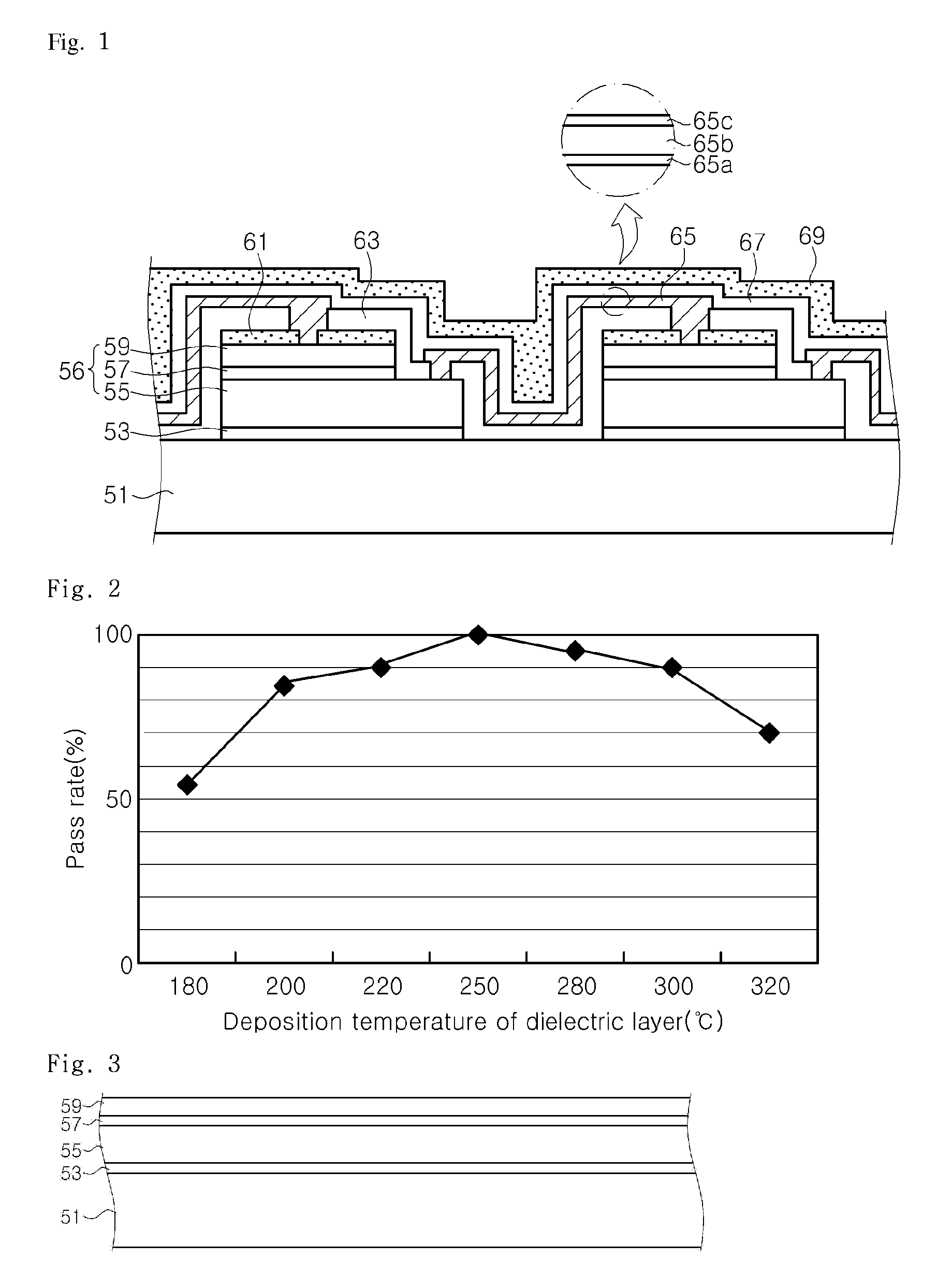
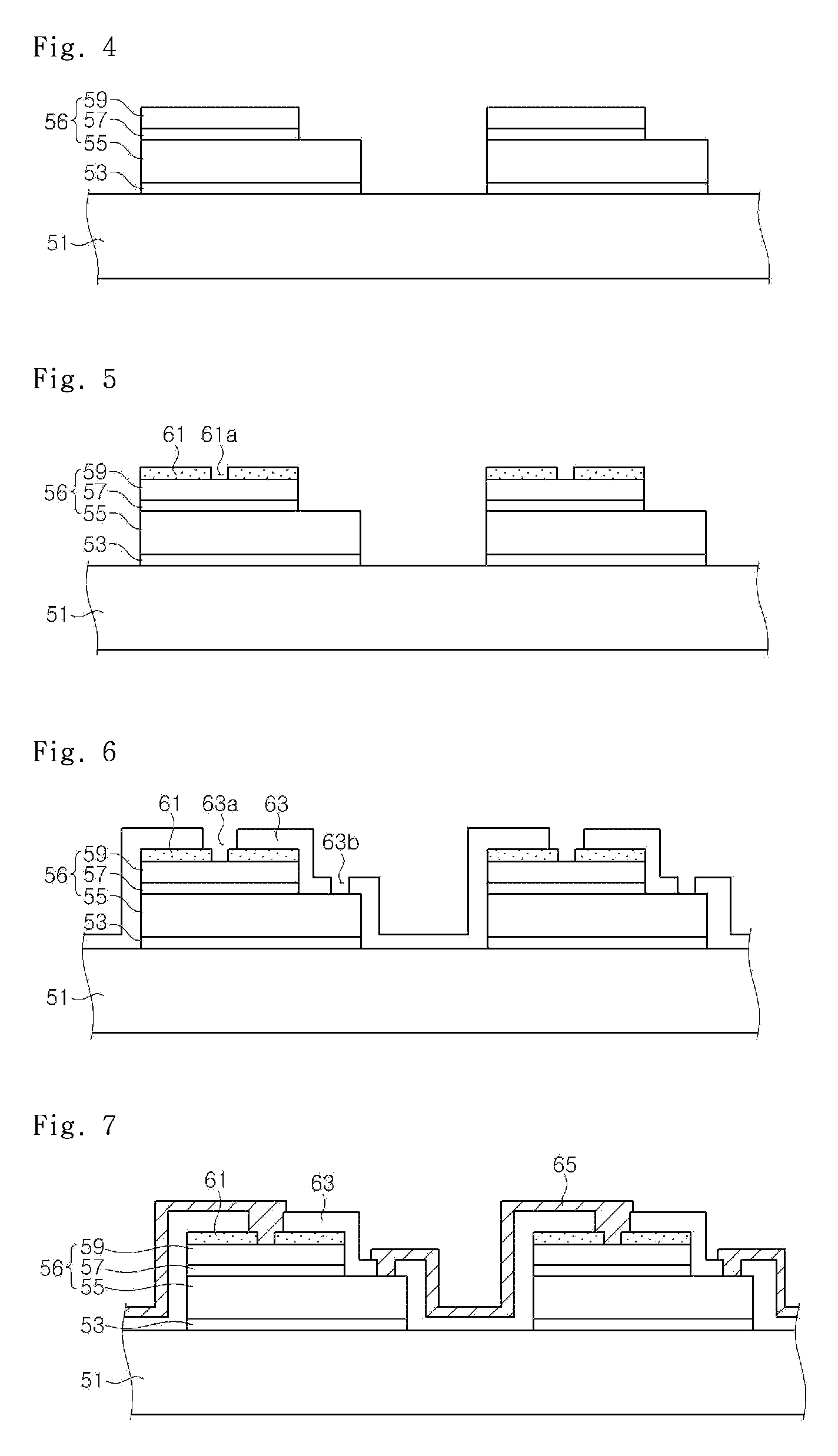
The present invention discloses a light emitting diode. The light emitting diode includes a plurality of light emitting cells arranged on a substrate, each light emitting cell including a first semiconductor layer and a second semiconductor layer arranged on the first semiconductor layer; a first dielectric layer arranged on each light emitting cell and including a first opening to expose the first semiconductor layer and a second opening to expose the second semiconductor layer; a wire arranged on the first dielectric layer to couple two of the light emitting cells; and a second dielectric layer arranged on the first dielectric layer and the wire. The first dielectric layer and the second dielectric layer comprise the same material and the first dielectric layer is thicker than the second dielectric layer.

Description

CROSS REFERENCE TO RELATED APPLICATIONS[0001]This application claims priority from and the benefit of Korean Patent Application No. 10-2008-0128522, filed on Dec. 17, 2008, which is hereby incorporated by reference for all purposes as if fully set forth herein.BACKGROUND OF THE INVENTION[0002]1. Field of the Invention[0003]The present invention relates to a light emitting diode and a method of fabricating the same. More particularly, the present disclosure relates to a light emitting diode that includes a plurality of light emitting cells, wires connecting the light emitting cells to each other, and dielectric layers for protecting the light emitting cells and the wires, and to a method of is fabricating the same.[0004]2. Discussion of the Background[0005]Since gallium nitride (GaN)-based blue light emitting diodes (LEDs) were developed, attempts have been made to improve luminescent efficiency of these LEDs, and a variety of structural improvements for various applications have bee...

Claims


Application Information

Patent Timeline
Patent Type & Authority Patents(United States)
IPC IPC(8): H01L29/18
CPCH01L27/153H01L24/24H01L33/44H01L33/507H01L33/62H01L2924/12041H01L2224/24137H01L2924/00H01L2224/82951
Inventor KAL, DAE SUNGKIM, DAE WONSEO, WON CHEOLYE, KYUNG HEELEE, JOO WOONG
Owner SEOUL SEMICONDUCTOR
Why Eureka
Try Eureka