Dual band resonator and dual band filter

a dual-band filter and resonator technology, applied in the direction of resonators, electrical equipment, waveguides, etc., can solve the problems of insufficient filtering of unwanted signals in frequency bands other than the desired pass band, difficulty in maintaining a high degree of freedom of design of four characteristic values, and disadvantageous dual-band filters

Inactive Publication Date: 2010-05-04
NTT DOCOMO INC
View PDF8 Cites 2 Cited by
  • Summary
  • Abstract
  • Description
  • Claims
  • Application Information

AI Technical Summary

Benefits of technology

[0012]A dual band filter can be provided that can be adjust the center frequency and the bandwidth, which is determined by the external coupling between the signal input / output line and the resonator, for each of the two pass bands to any values without decreasing the degree of freedom of setting of the values, can effectively remove unwanted signals in the frequency bands other than the desired pass bands, and can be downsized.

Problems solved by technology

Therefore, in designing and constructing the dual band filter, maintaining high degree of freedom of design of the four characteristic values is difficult.
The dual band filter shown in FIG. 15 has a problem that unwanted signals in the frequency bands other than the desired pass bands cannot be adequately filtered out because the input / output transmission lines are directly connected to each other, and an additional band pass filter is needed to completely remove the signals in the unwanted frequency bands.
In addition, from the viewpoint of downsizing of the filter, the dual band filter is disadvantageous because transmission lines of certain lengths are connected to each other at the ends.

Method used


Image

  • Dual band resonator and dual band filter
  • Dual band resonator and dual band filter
  • Dual band resonator and dual band filter

Examples


first embodiment

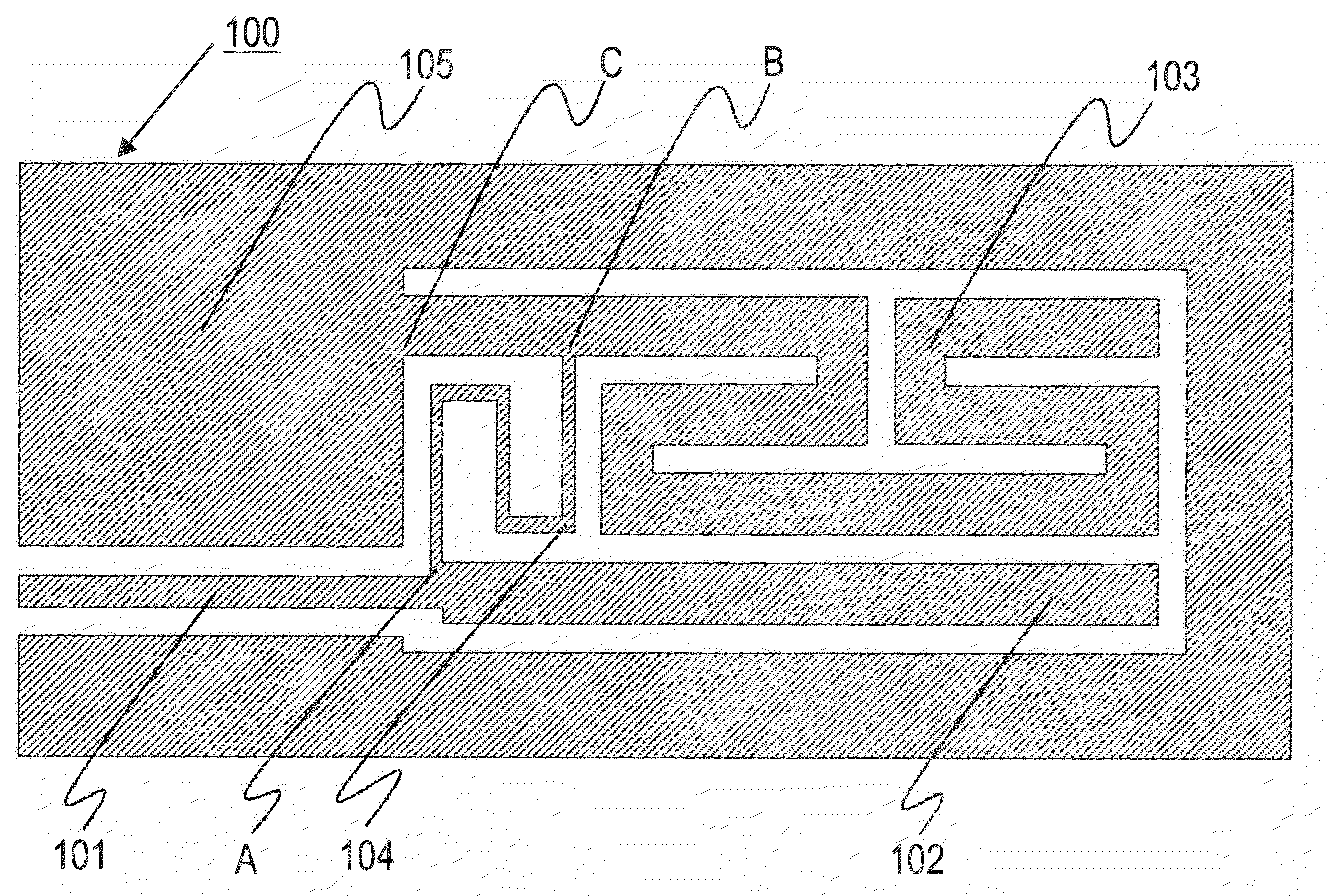
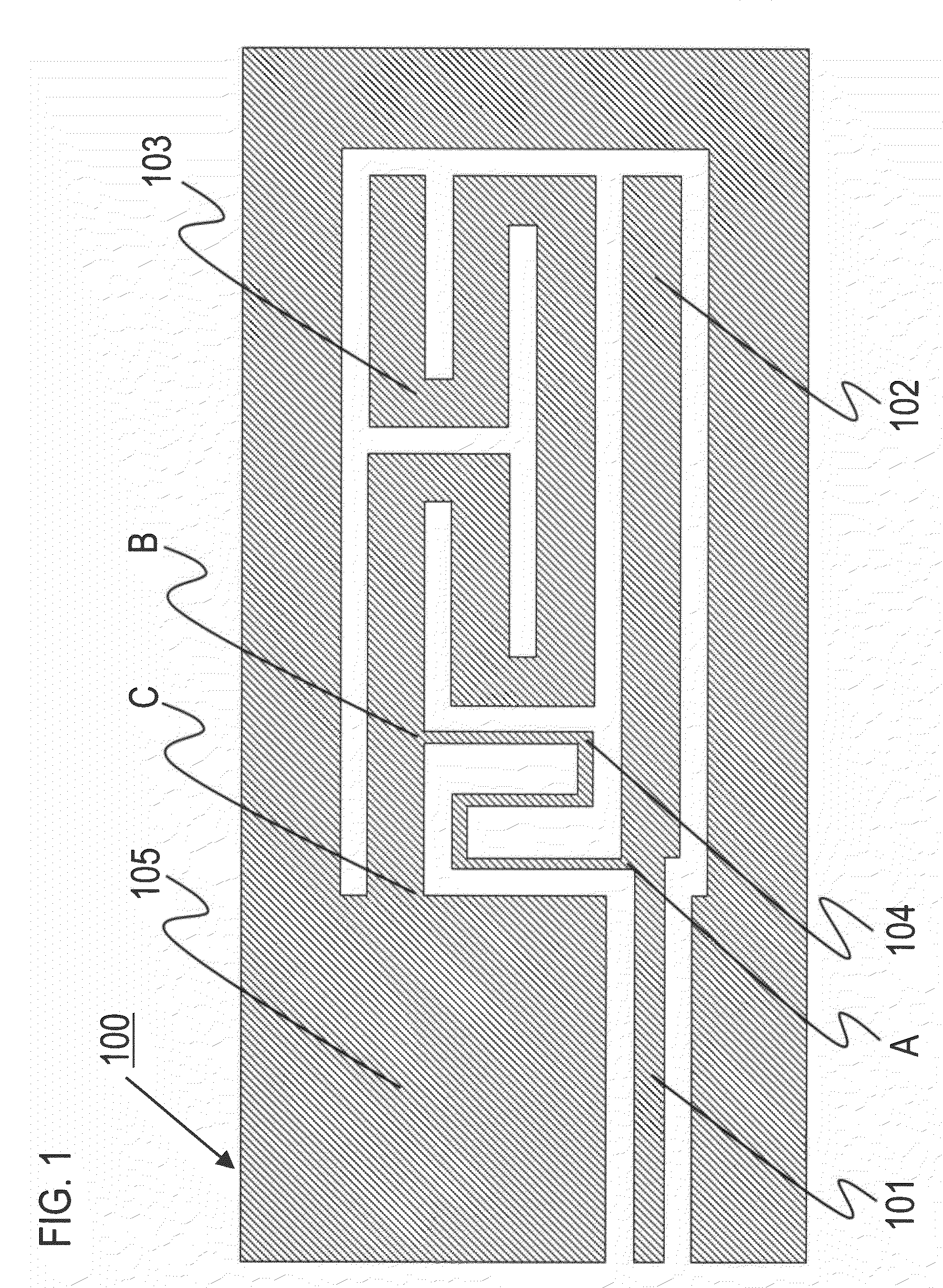
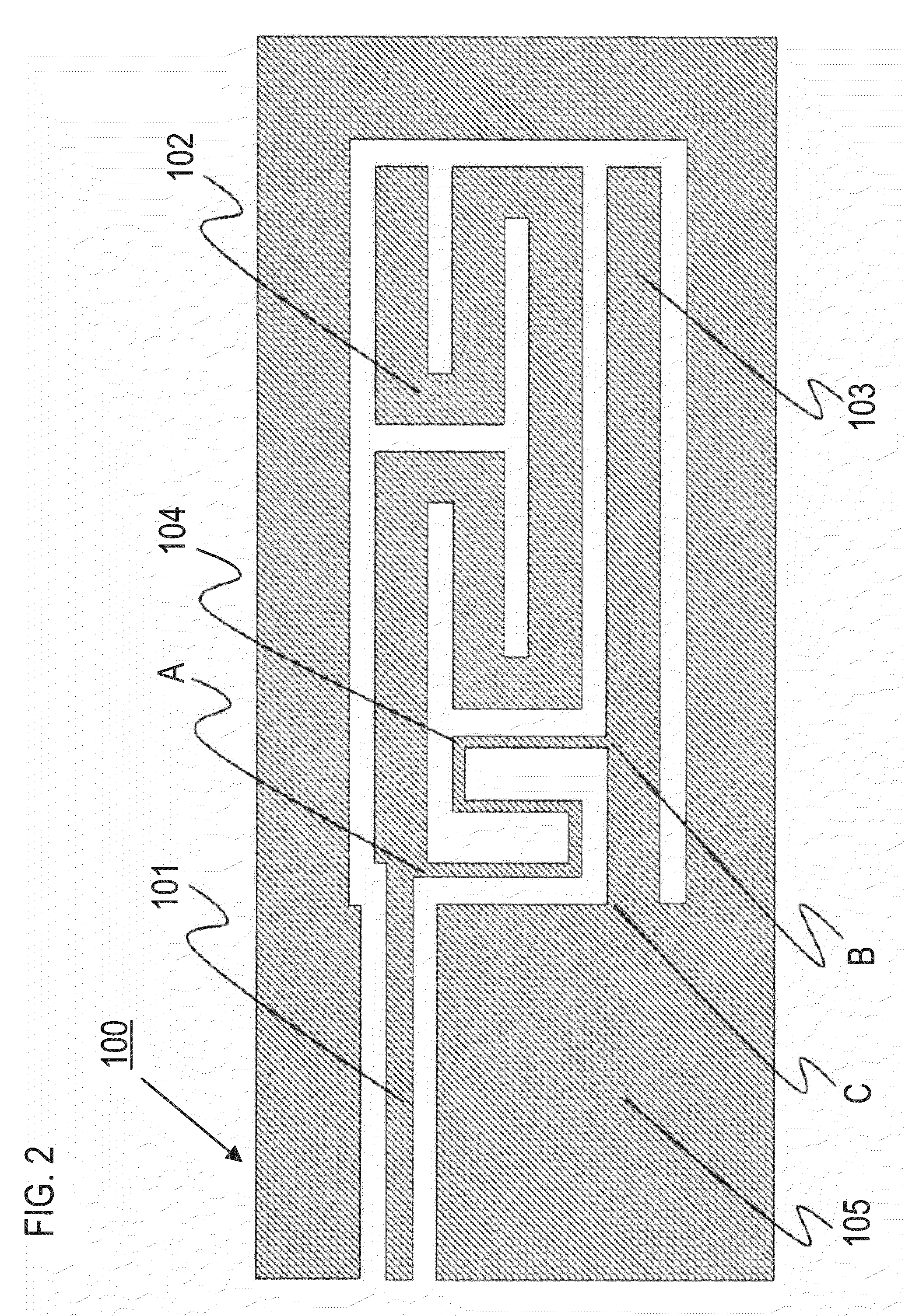
[0029]FIG. 1 shows a configuration of a resonator according to a first embodiment. In this drawing, the shaded parts represent regions covered with a conductor, and the white parts outlined by the shaded parts represent regions in which a dielectric substrate below the conductor is exposed. The same holds true for all the drawings described below.

[0030]A resonator 100 has a signal input / output line 101, a first resonating part 102, a second resonating part 103 and a first connecting line 104 and is formed in a coplanar plane circuit having ground conductors on the opposite sides thereof.

[0031]The signal input / output line 101 is used for signal input and output. The first resonating part 102 is connected to the signal input / output line 101 at one end and is opened at the other end. The second resonating part 103 is connected at one end to the ground conductor 105 at a point of connection C and is opened at the other end. The first resonating part 102 and the second resonating part 10...

second embodiment

[0037]FIG. 3 shows a configuration of a resonator according to a second embodiment.

[0038]A resonator 200 is composed of a signal input / output line 101, a first resonating part 202, a second resonating part 203 and a first connecting line 104. The signal input / output line 101 and the first connecting line 104 are the same as those in the embodiment 1 described above. In this way, of the parts shown in FIG. 3, those having the same name and the same function as those shown in FIG. 1 are denoted by the same reference numerals, and descriptions thereof will be omitted. The same holds true for the other drawings.

[0039]The first resonating part 202 and the second resonating part 203 are the same as the first resonating part 102 and the second resonating part 103 according to the first embodiment, respectively, in that the first resonating part 202 is connected to the signal input / output line 101 at one end and is opened at the other end, the second resonating part 203 is connected at one ...

third embodiment

[0043]FIG. 4 shows a configuration of a resonator according to a third embodiment.

[0044]A resonator 300 is composed of a signal input / output line 101, a first resonating part 302, a second resonating part 303 and a first connecting line 104. The signal input / output line 101 and the first connecting line 104 are the same as those according to the first embodiment described above.

[0045]The first resonating part 302 and the second resonating part 303 are the same as the first resonating part 102 and the second resonating part 103 according to the first embodiment, respectively, in that the first resonating part 302 is connected to the signal input / output line 101 at one end and is opened at the other end, the second resonating part 303 is connected at one end to a ground conductor 105 at a point of connection C and is opened at the other end, and the first resonating part 302 and the second resonating part 303 have different resonance frequencies.

[0046]However, in the third embodiment,...


PUM


Abstract

A signal input / output line 101 is used for input and output of a signal. A first resonating part 102 is connected to the signal input / output line 101 at one end and is opened at the other end. A second resonating part 103 is connected to a ground conductor 105 at one end and is opened at the other end. A connecting line 104 has a predetermined length and is connected to a point of connection between the signal input / output line 101 and the first resonating part 102 at one end and is connected to a predetermined point on the second resonating part 103 at the other end.

Description

TECHNICAL FIELD[0001]The present invention relates to a dual band resonator and a dual band filter mainly used for a plane circuit for the microwave band or millimeter wave band.BACKGROUND ART[0002]In general, conventional dual band filters having two pass bands can be classified into two types in terms of configuration.[0003]One type is a filter composed of dual band resonators that have an appearance of one integral unit, resonate at two frequencies and are coupled to the input / output ports and further dual band resonators coupled thereto, such as the filter shown in FIG. 14 (see the non-patent literature 1, for example). For this filter, the structure and the dimensions of the coupling parts of the dual band resonators disposed at the opposite ends and coupled to the input / output line have to be determined to achieve a desired center frequency and a desired bandwidth for each of the two bands.[0004]The other type is a filter composed of a plurality of transmission lines having di...

Claims


Application Information

Patent Timeline
Patent Type & Authority Patents(United States)
IPC IPC(8): H01P1/203H01P3/08
CPCH01P1/2013H01P7/08H01P1/203H03H7/01H03H9/46
Inventor KOIZUMI, DAISUKESATOH, KEINARAHASHI, SHOICHI
Owner NTT DOCOMO INC
Why Eureka
Try Eureka