Optical polarizer and method for fabricating the same

a technology of optical polarizers and polarizing elements, applied in the field of optical polarizers, can solve the problem of not having a uniform polarization property in the entire electromagnetic wavelength region

Active Publication Date: 2010-05-04
TSINGHUA UNIV +1
View PDF6 Cites 79 Cited by
  • Summary
  • Abstract
  • Description
  • Claims
  • Application Information

AI Technical Summary

Problems solved by technology

Besides, the conventional optical polarizers can achieve good polarization property in a certain region of wavelength (e.g. microwave, infrared, visible light, ultraviolet, etc.), but can't have a uniform polarization property in the entire electromagnetic wavelength region.

Method used


Image

  • Optical polarizer and method for fabricating the same
  • Optical polarizer and method for fabricating the same
  • Optical polarizer and method for fabricating the same

Examples


Embodiment Construction

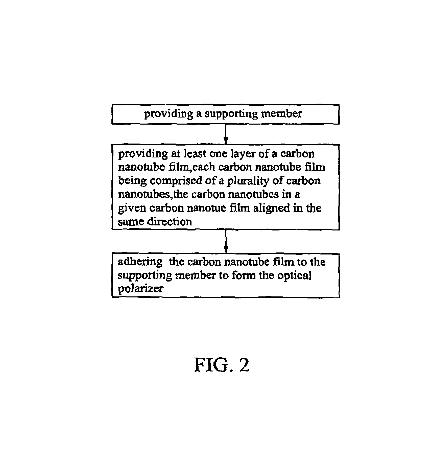
[0021]Reference will now be made to the drawings to describe, in detail, embodiments of the present optical polarizer and the related method for fabricating the same.

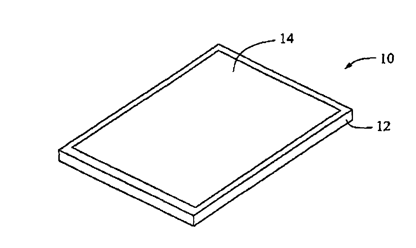
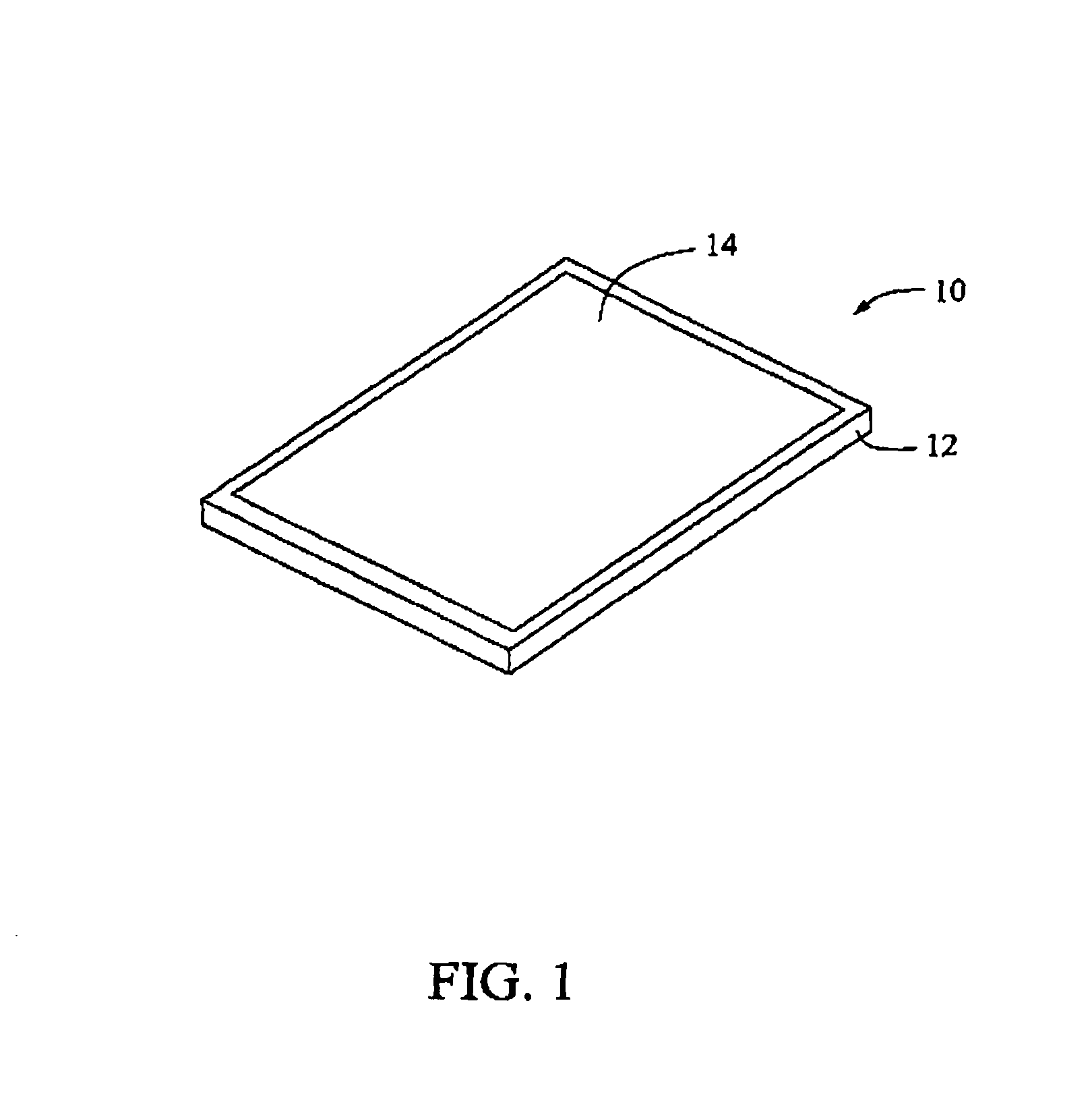
[0022]Referring to FIG. 1, an optical polarizer 10 in the present embodiment includes a supporting member 12 and a carbon nanotube film 14 supported by the supporting member 12. The supporting member 12 can, beneficially, be a frame or a transparent substrate. A schematic view of the carbon nanotube film 14 located on the transparent substrate can be seen in FIGS. 6 and 7. The carbon nanotube film 14 can, opportunely, be directly adhered to the frame or a surface of the transparent substrate. The carbon nanotube film 14 includes a plurality of successive aligned carbon nanotube bundles joined end to end. The carbon nanotube film 14 can, optionally, be a single layer film or a multi-layer film. The carbon nanotube bundles in different layers of the carbon nanotube film are aligned in the same direction.

[0023]A width of t...


PUM

PropertyMeasurementUnit
thicknessaaaaaaaaaa
widthaaaaaaaaaa
heightaaaaaaaaaa

Abstract

An optical polarizer includes a supporting member and a polarizing film supported by the supporting member. The polarizing film includes at least one layer of a carbon nanotube film, and the carbon nanotubes in a given carbon nanotube film are aligned in the same direction therein. A method for fabricating the optical polarizer includes the steps of: (a) providing a supporting member; (b) providing at least one layer of a carbon nanotube film, the carbon nanotubes in a given carbon nanotube film aligned along the same direction; and (c) adhering a given carbon nanotube film to the supporting member to form the optical polarizer.

Description

RELATED APPLICATIONS[0001]This application is related to commonly-assigned applications entitled, “CARBON NANOTUBE FILM STRUCTURE AND METHOD FOR FABRICATING THE SAME”, Ser. No. 12 / 002,129, filed Dec. 14, 2007, “ANODE OF LITHIUM BATTERY AND METHOD FOR FABRICATING THE SAME”, Ser. No. 12 / 002,143, filed Dec. 14, 2007, and “FIELD EMISSION CATHODE AND METHOD FOR FABRICATING THE SAME”, Ser. No. 12 / 002,144, filed Dec. 14, 2007. Disclosures of the above-identified applications are incorporated herein by reference.BACKGROUND[0002]1. Field of the Invention[0003]The present invention relates to optical components and methods for fabricating the same and, particularly, to an optical polarizer and a method for fabricating the same.[0004]2. Discussion of Related Art[0005]The optical polarizing film is widely used for glare reduction and for increasing optical contrast in such products as sunglasses and liquid crystal displays (LCDs). One of the most common polarizers is a dichroic / dichromatic pola...

Claims


Application Information

Patent Timeline
Patent Type & Authority Patents(United States)
IPC IPC(8): G02B5/30
CPCG02B5/3058G02B5/3008Y10S977/742Y10S977/746
Inventor FENG, CHENJIANG, KAI-LILIU, LIANGZHANG, XIAO-BOFAN, SHOU-SHAN
Owner TSINGHUA UNIV
Why Eureka
Try Eureka