Method and apparatus for optimization of redundant link usage in a multi-shelf network element

Inactive Publication Date: 2010-05-04
RPX CORP +1
View PDF46 Cites 12 Cited by
  • Summary
  • Abstract
  • Description
  • Claims
  • Application Information

AI Technical Summary

Problems solved by technology

The simplex differential channel is used instead of the TDM channel or the Ethernet channel because the RTS is sensitive to time delays that result from the applications running on the TDM and Ethernet channels.
However, if at any time the work link becomes inoperable or defective, the receiving component immediately begins processing the data received over the “protection”

Method used


Image

  • Method and apparatus for optimization of redundant link usage in a multi-shelf network element
  • Method and apparatus for optimization of redundant link usage in a multi-shelf network element
  • Method and apparatus for optimization of redundant link usage in a multi-shelf network element

Examples


Embodiment Construction

[0041]A method and apparatus for optimizing redundant link usage in a multi-shelf network element is disclosed. In the following description, numerous specific details are set forth to provide a thorough description of the invention. However, it will be apparent to one skilled in the art that the invention may be practiced without these specific details. In other instances, well-known features have not been described in detail so as not to obscure the invention.

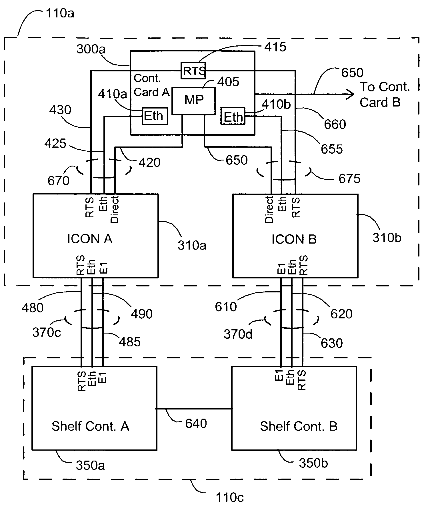
[0042]FIGS. 5A and 5B show intershelf control data path connections between two shelves of a multi-shelf element in an embodiment of the invention. FIG. 5A shows the control data path connections between control card A 300a in peripheral shelf 1110a and shelf controller A 350a of peripheral I / O shelf 110c. These control data path connections are the same as those of FIG. 4, in simplified form. In addition, FIG. 5B shows a similar control data path between control card A 300a and shelf controller B 350b in peripheral I / O shelf...


PUM


Abstract

A method and apparatus for optimizing redundant link usage allows a portion of the wasted bandwidth in a redundant link system to be utilized for additional data traffic without compromising the ability of the system to respond to and correct for a failure of a link. In one embodiment, one of two independent, individually addressable links is selected as a nominal communication path, and the other as a standby communication path. The path independent traffic is sent via the nominal communication path, while the path dependent data is sent via the nominal communication path or the standby path, in accordance with the dependence of the traffic. In another embodiment, critical time sensitive traffic is sent via a nominal and standby time sensitive paths, while normal traffic is sent via nominal normal path, and non-critical traffic is sent via a standby normal path.

Description

RELATED APPLICATIONS[0001]This application claims the benefit of U.S. Provisional Application No. 60 / 325,368, filed Sep. 27, 2001.FIELD OF THE INVENTION[0002]The present invention relates to the field of network elements, and more particularly to a method and apparatus for optimization of redundant link usage in a multi-shelf network element.BACKGROUND OF THE INVENTION[0003]1. Multi-Shelf Network Elements[0004]An example of a multi-shelf network element with which the present invention may be used is multi-shelf switch system 100 shown in schematic block form in FIG. 1. Switch system 100 comprises peripheral shelves 110a-n, switching shelves 120a-b, and control complex 130. Peripheral shelves 110a-n provide input / output (I / O) interfaces for connection to data paths 115a-n for which switching services are provided by switch system 100. Switching shelves 120a-b provide the switching services for the system. Control complex 130 provides central management for the switch system. The var...

Claims


Application Information

Patent Timeline
IPC IPC(8): H04L12/26G01R31/08G06F11/00G08C15/00H04J1/16H04L12/56H04L69/40H04Q11/00
CPCH04L45/02H04L45/22H04L45/30H04L45/70H04L45/24H04Q2011/0081
Inventor SOETEMANS, JOSEPHPIKE, DIONFRIESEN, LARRYLABONTE, JEAN
Owner RPX CORP
Why Eureka
Try Eureka