Three-dimensional image measuring apparatus and method

a three-dimensional image and measuring apparatus technology, applied in the direction of image enhancement, instruments, using wave/particle radiation means, etc., can solve the problems of serious disturbance noise, the details of the measuring object and its surroundings cannot be known, and the measurement of objects with significant projections and depressions is difficult to measur

Inactive Publication Date: 2010-05-04
KK TOPCON
View PDF8 Cites 22 Cited by
  • Summary
  • Abstract
  • Description
  • Claims
  • Application Information

AI Technical Summary

Benefits of technology

[0013]With this configuration, the image search area setting section 56 sets a reference area 57 in one image 53 of a pair of stereo images 46 and a search area 58 in the other image 54 in a position corresponding to the reference area 57, as a preprocess for obtaining the positional relationship with respect to the search area 58 corresponding to the reference area 57. The search image correcting section 62 applies an image distortion correction to either one of the one image 53 or the other image 54 according to the positional relationship between the reference are 57 and the search area 58 corresponding to the reference area 57, so that the positional correspondence can be easily achieved in consideration of image distortion included in the pair of stereo images 46 and attributable to the distortion of the optical system, image blur, the shadow on the measuring object 41 and the like. The area shape measuring section 66 measures a shape of the measuring object 41 photographed in the stereo images 46 based on the reference area 57 in the one image 53 and the search area 58 in the other image 54, either one of which has been corrected by the search image distortion correcting section 62.
[0014]Preferably, the three-dimensional image measuring apparatus of the present invention may further comprise, as shown in FIG. 1 for example, a unitary geometric shape network forming section 60 for forming a unitary geometric shape network that covers the one image 53 and the other image 54 of the stereo images 46 by duplicating a unitary geometric shape two-dimensionally, wherein the reference area 57 and the search area 58 set by the image search area setting section 56 are of the unitary geometric shape, and the search image distortion correcting section 62 corrects a distortion of the search area 58 with respect to the reference area 57. When the one image 53 and the other image 54 of the stereo images 46 are covered with a unitary geometric shape network, grid points of the unitary geometric shape and with a generally uniform density are distributed over the entire region of the one image 53 and the other image 54 covered with the unitary geometric shape network. The search image distortion correcting section 62 corrects the distortion of the search area 58 with respect to the reference area 57 over the entire region covered with the unitary geometric shape network, thereby distributing the image distortion to the respective grid points of the unitary geometric shape. This allows the area shape measuring section 66 to yield reasonable results from the measurement of a shape of the measuring object 41 photographed in the stereo images 46.
[0017]Preferably, in the three-dimensional image display apparatus of the present invention as shown in FIG. 1 and FIG. 4 for example, the unitary geometric shape network forming section 60 may form coarse to fine geometric shapes and bay be configured to sequentially form a finer geometric shape from a coarser geometric shape for an image distortion correction. With this configuration, an approximate image distortion correction is performed with a coarse geometric shape, and then a more precise image distortion correction is performed with a finer geometric shape, using the results of the approximate image distortion correction. In this manner, reliable image distortion correction can be performed with a small amount of calculation.
[0025]With a three-dimensional image measuring apparatus and method of the present invention, projections and depressions on a surface of an object can be measured with fine precision, as well as stable convergence can be ensured, even for stereo images with significant project distortion. Images with significant projection distortion include central projection images resulting from measurement at relatively short to middle distances, and parallel projection images in which significant ups and downs are captured. Typical examples of the latter include, for example, photographing of semiconductor samples and objects with such projections and depressions that significantly affect the photographing distance.

Problems solved by technology

However, since the bare information which can be acquired includes no image but only distance data and angle data, the details of the measuring object and its surroundings cannot be known.
The former approach also involves a serious problem of disturbance noise due to long hours of installation for measurement.
However, measuring objects with significant projections and depressions are difficult to measure in both approaches.
It has become apparent with the latter approach, that photographed images of some measuring objects, in particular at short to middle distances, are not a little affected by projection distortion due to their projections and depressions, and that it is therefore difficult to perform precise three-dimensional position measurement using such images.

Method used


Image

  • Three-dimensional image measuring apparatus and method
  • Three-dimensional image measuring apparatus and method
  • Three-dimensional image measuring apparatus and method

Examples


first embodiment

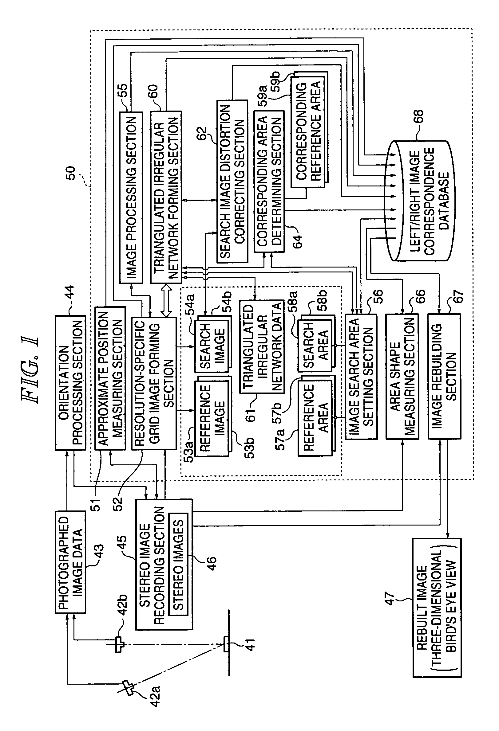
[0047]FIG. 1 is a block diagram illustrating the general configuration of a three-dimensional image measuring apparatus of the present invention. In the figure, a measuring object 41 is photographed by cameras 42a, 42b with the same optical properties. The cameras 42a, 42b as an imaging optical system have a known focal length with their lens aberrations compensated, and are disposed such that the object 41 is photographed by the left and right stereo cameras 42a, 42b with the same resolution. The left and right stereo cameras 42a, 42b generate a pair of stereo-photographed image data 43 on the object 41, with a high overlap rate of, for example, not less than 60%. The cameras may be an optical type using general-purpose film, or an electronic type like a CCD (Charged Couple Device). For smooth image processing, the stereo-photographed image data 43 are preferably stored as electromagnetically recorded information in a flexible disk, a CDROM, a DVD or the like.

[0048]An orientation p...

second embodiment

[0084]FIG. 15 is a block diagram illustrating the general configuration of a second embodiment of the three-dimensional image measuring apparatus of the present invention. In the first embodiment, the search image distortion correcting section 62 corrects the search image 54 with the search image distortion correction amount, with the image distortion of the reference image 53 left untouched. However, in cases where the image distortion of the reference image 53 is significant, it may be preferable that the image distortion of the reference image 53 is also corrected in consideration of that of the search image 54. Thus, the second embodiment addresses a case where the image distortion of the reference image 53 is also corrected.

[0085]In the figure, components having the same functions as those in FIG. 1 are given the same reference numerals and symbols, and descriptions of such components will not be repeated. An image measuring device 70 includes a reference area deforming section...


PUM


Abstract

The present invention provides a three-dimensional image measuring apparatus and method capable of measuring projections and depressions on a surface of an object with fine precision, as well as ensuring stable convergence, even for stereo images with significant project distortion. The apparatus includes an area setting section 56 for setting a reference area 57 in one image 53 of a pair of stereo images 46 and a search area 58 in the other image 54 in a position corresponding to the reference area 57, a search image distortion correcting section 62 for applying an image distortion correction to either one of the one image 53 or the other image 54 according to the positional relationship between the reference area 57 and the search area 58 corresponding to the reference area 57, and an area shape measuring section 66 for measuring a shape of a measuring object 41 photographed in the stereo images 46 based on the reference area 57 in the one image 53 and the search area 58 in the other image 54, either one of which has been corrected by the search image distortion correcting section 62.

Description

BACKGROUND OF THE INVENTION[0001]1. Technical Field[0002]The present invention relates to a three-dimensional image measuring apparatus and method for acquiring three-dimensional shape data on a measuring object using photographed image data. The present invention is directed to image measurement of measuring objects at short to middle distances, where significant projection distortion occurs in images photographed in stereo, rather than long-distance objects such as in aerial photography.[0003]2. Related Art[0004]Methods for obtaining 3D data on a working object, a manufacturing object or geographic features include an approach using a measuring instrument (total station) that obtains 3D data at points based on the distance and angle to an object, a motor-driven measuring instrument that acquires data in a surface manner by scanning with a beam, or a laser scanner that acquires data by rapidly oscillating a laser beam.[0005]Meanwhile, other methods include a stereo image measuremen...

Claims


Application Information

Patent Timeline
Patent Type & Authority Patents(United States)
IPC IPC(8): G06K9/00G06K9/32G06K9/36G06T15/00G01B15/00G01B7/00G01B11/24G06T1/00G06T3/00G06T5/00G06T7/00
CPCG06T5/006G06T7/0026G06T7/0075G06T2207/30181G06T2207/10012G06T2207/20016G06T7/32G06T7/593
Inventor ITO, TADAYUKIOTANI, HITOSHIKOCHI, NOBUO
Owner KK TOPCON
Why Eureka
Try Eureka