Turbine blade assembly

a technology of turbine blades and assemblies, which is applied in the direction of electric generator control, marine propulsion, and vessel construction, etc., can solve the problems of increased blade weight, increased total head mass of the turbine system, and increased economic hardship and instability, so as to reduce the cost of the turbine, and reduce the overall weight of the turbin

Inactive Publication Date: 2010-05-11
LIAO NING
View PDF17 Cites 5 Cited by
  • Summary
  • Abstract
  • Description
  • Claims
  • Application Information

AI Technical Summary

Benefits of technology

[0019]Accordingly, turbine designs in accordance with the foregoing principles will be able to reduce the overall turbine weight, and hence reduce the cost of turbines. Moreover, such designs achieve larger diameters and turbines with a larger number of blades. Also, such turbines can be built with less expensive materials or processes.

Problems solved by technology

In particular, reliance on foreign crude oil as an energy source has tended to cause economic hardship and instability because the price of crude oil can vary dramatically based on a number of unpredictable geopolitical and economic factors.
This directly increases the weight of the blades, resulting in heavier total head mass for the turbine systems, which translates into higher turbine system costs.
Blade tip speed is one of the major constraints that limit the size of the current three-blade wind turbine.
The increase of tip speed ratio will result in the decease of turbine efficiency.
However, increasing the number of blades will increase the massiveness of the turbine and the turbine weight, so that attempts to increase the number of blades is difficult with today's design.
Composite materials are relatively new and are not that well understood compared with the traditional material like metals.
Also, the composite materials usually require special manufacturing processes that are more costly.
But these known designs attach the cables to the blades in a rudimentary way (e.g., U.S. Pat. No. 4,403,916), resulting in blades which cannot be rotated around their axes to adjust pitch.
So pitch controllers cannot be used in such designs.

Method used


Image

  • Turbine blade assembly
  • Turbine blade assembly
  • Turbine blade assembly

Examples


Embodiment Construction

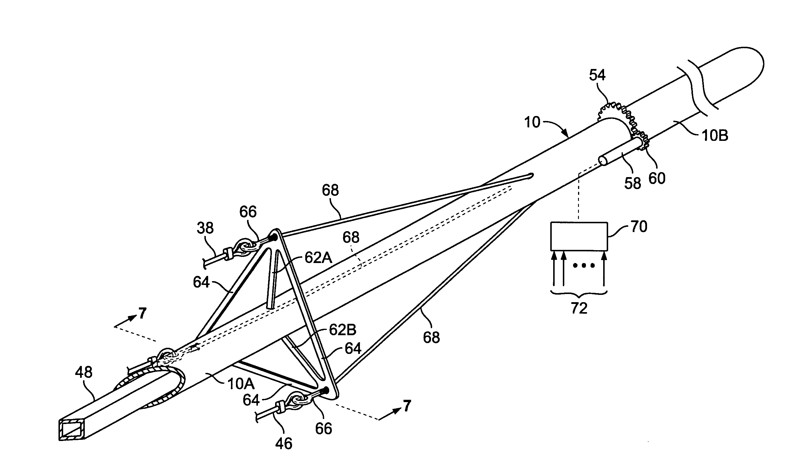
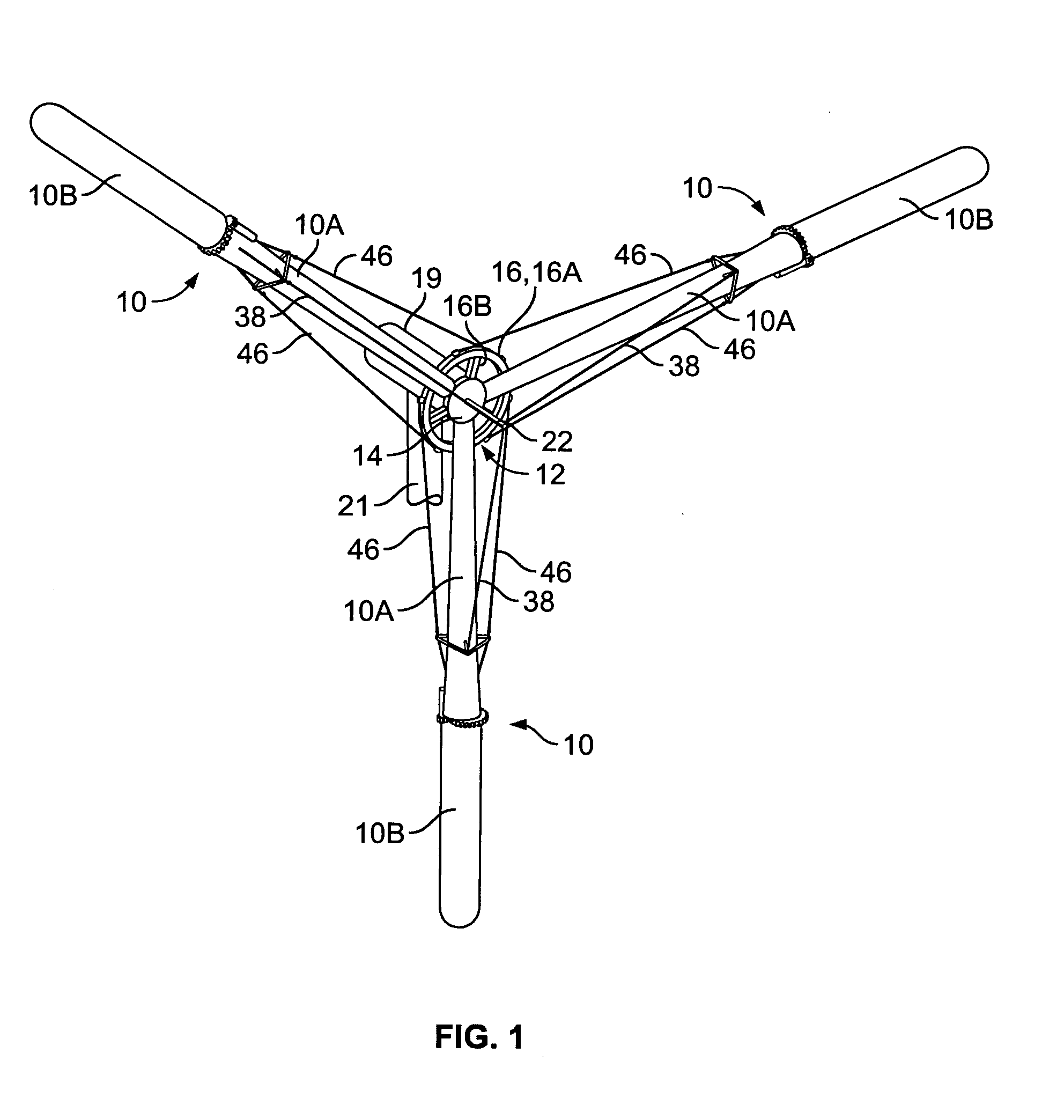
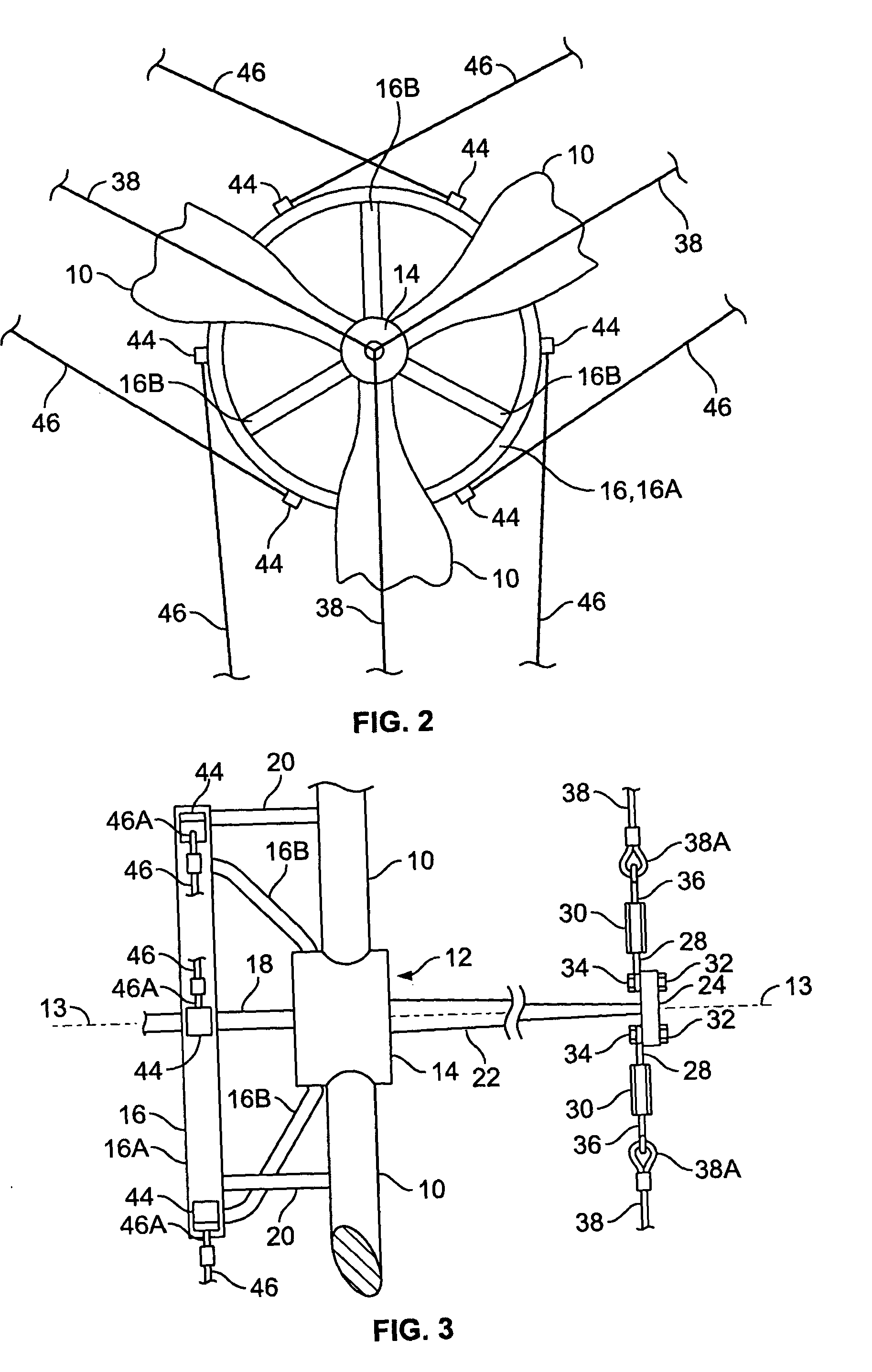
[0029]Referring to FIGS. 1-3, a turbine blade assembly is shown as a trio of equiangularly spaced blades 10 extending radially outward from a central rotor 12. Rotor 12 is shown with a hub 14 supporting the roots of blades 10.

[0030]Blades 10 each have a proximal section 10A and a variable pitch section 10B. Blades 10B are shown in an operating position with a moderate pitch angle (for example, an angle in the range of 10 to 30°). In some embodiments blades 10B can rotate from the illustrated pitch to a pitch of 90° where the blades produce no power (i.e., a parked position) or a reverse pitch to counterbalance any torque that may be produced by the proximal section 10A. FIG. 7 indicates the pitch angle is measured with respect to the plane of blade rotation P.

[0031]Hub 14 is a central element of a dished wheel 16 having a rim 16A connected by three curved spokes 16B to hub 14. Three braces 20 extend axially from the rim 16A to blades 10 to reinforce them. A coaxial drive shaft 18 co...


PUM


Abstract

A turbine blade assembly has a plurality of blades mounted on a central rotor. Each of the blades has a proximal section and a variable pitch section. A number of stays extend in groups from the central rotor to converge and terminate on an associated one of the blades. The stays each have a proximal end spaced from the blades.

Description

BACKGROUND OF THE INVENTION[0001]1. Field of the Invention[0002]The present invention relates to turbine blade assemblies, and in particular, to assemblies reinforced with stays.[0003]2. Description of Related Art[0004]Independence from foreign energy sources is highly desirable. In particular, reliance on foreign crude oil as an energy source has tended to cause economic hardship and instability because the price of crude oil can vary dramatically based on a number of unpredictable geopolitical and economic factors.[0005]In some regions wind power is a viable domestic energy source. Known wind-driven turbines employ rather long turbine blades that rotate an electrical generator. The entire wind turbine can be mounted on a high tower to provide clearance for large blades and to expose the blades to more dependable winds existing at a higher elevations.[0006]In any event, the economic viability of the wind turbine depends greatly on the capital cost in comparison to the energy genera...

Claims


Application Information

Patent Timeline
Patent Type & Authority Patents(United States)
IPC IPC(8): F03D11/00
CPCF03D1/0675F03D7/0228F05B2240/2021Y02E10/723F05B2260/74Y02E10/721F05B2260/50Y02E10/72
Inventor LIAO, NING
Owner LIAO NING
Why Eureka
Try Eureka