Ultrasonic sensor

a technology of ultrasonic sensor and sensor body, applied in the direction of reradiation, pedestrian/occupant safety arrangement, instruments, etc., to achieve the effect of reducing vibration, accurate positioning of each sensor element, and improving the positioning accuracy of multiple sensor elements

Inactive Publication Date: 2010-05-11
DENSO CORP
View PDF31 Cites 3 Cited by
  • Summary
  • Abstract
  • Description
  • Claims
  • Application Information

AI Technical Summary

Benefits of technology

[0008]In view of the above and other difficulties, it is an objective of the present invention to provide an ultrasonic sensor with high positioning accuracy of sensor elements and lower ultrasonic wave attenuation.
[0010]According to the above ultrasonic sensor, since the ultrasonic sensor includes the bonding member having the thickness approximately equal to the space interval between the adjacent ultrasonic sensing elements, the space interval between each adjacent ultrasonic sensing elements cam be precisely maintained. Therefore it is possible to accurately position each sensor element at a predetermined position. That is, it is possible to improve positioning accuracy of the multiple sensor elements. Further, since the elastic modulus of the portion of the bonding member contacting each ultrasonic sensing element is smaller than that of each ultrasonic sensing element, the bonding member does not strongly restrain vibrations in the ultrasonic sensing elements. Therefore, in the ultrasonic sensor, detection sensitivity for the ultrasonic wave can be maintained at a favorable condition. Further, since vibration conduction between the ultrasonic sensing elements hardly occurs, the ultrasonic wave is separately and individually conducted in each sensor element. Accordingly, vibration noise and ultrasonic wave attenuation are reduced. Therefore, the ultrasonic sensor has a favorable cross talk characteristic.

Problems solved by technology

Further, since the elastic modulus of the portion of the bonding member contacting each ultrasonic sensing element is smaller than that of each ultrasonic sensing element, the bonding member does not strongly restrain vibrations in the ultrasonic sensing elements.

Method used


Image

  • Ultrasonic sensor
  • Ultrasonic sensor
  • Ultrasonic sensor

Examples


first embodiment

Effect of First Embodiment

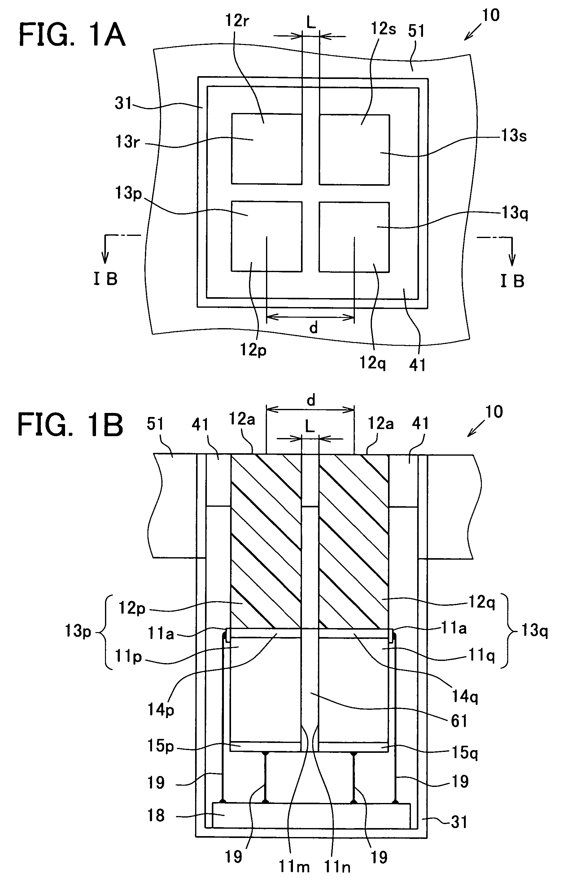
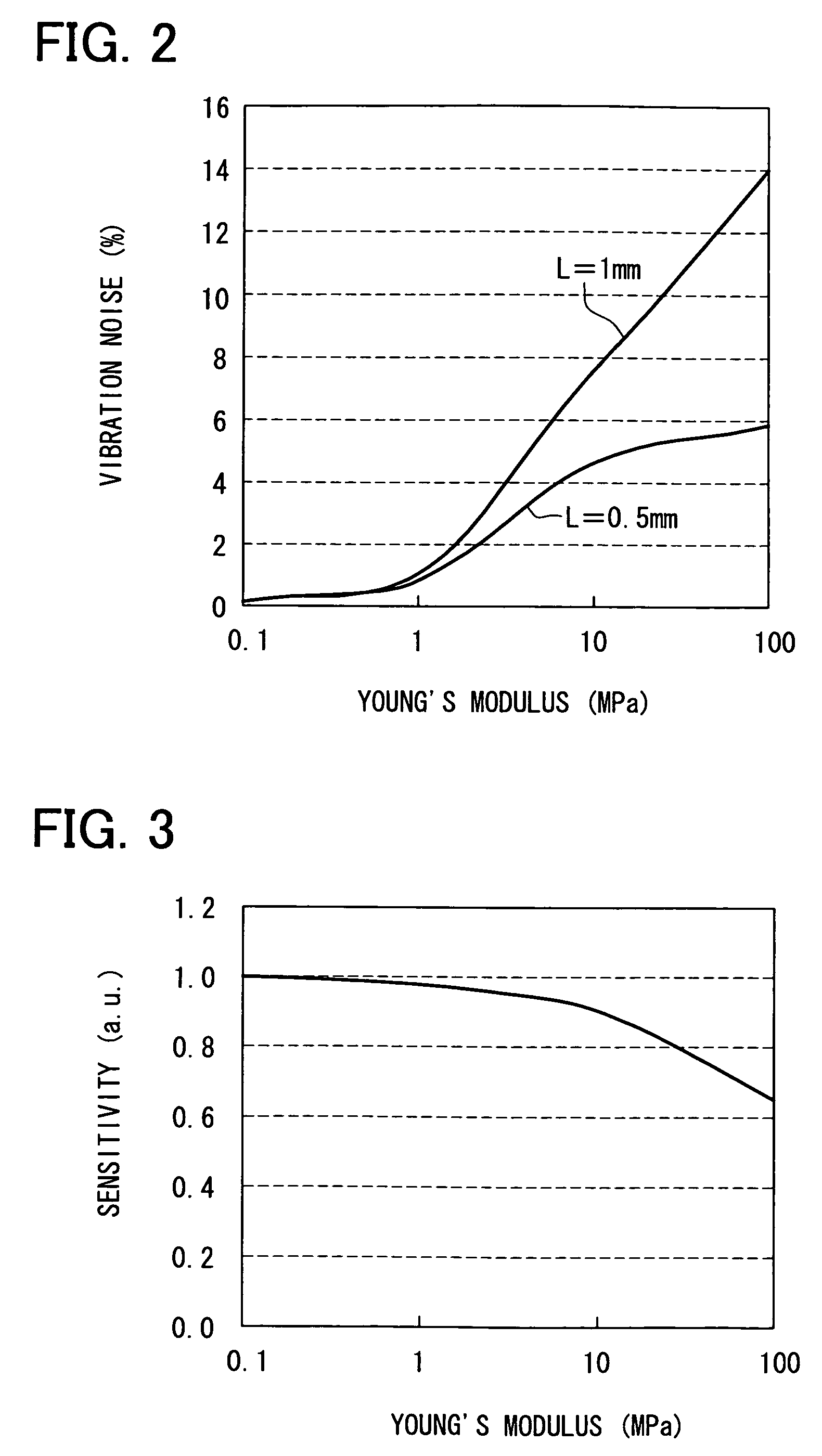
[0058]The bonding member 61 has a thickness approximately equal to the space intervals between the piezoelectric elements 11p to 11s. The piezoelectric elements 11p to 11s are bonded in such a state that the bonding member 61 fixes each adjacent piezoelectric elements 11p to 11s and precisely maintains the space intervals. Therefore, it is possible to accurately position each piezoelectric element 11p to 11s at a desired position. Because of the accurate positioning, it is possible to improve accuracy for detecting a distance to an object and a location of the object. Since the bonding member 61 is made of a material whose elasticity is lower than that of each piezoelectric element 11p to 11s, the bonding member 61 does not substantially restrict vibrations in each piezoelectric element 11p to 11s. Therefore, the ultrasonic sensor 10 maintains the detection sensitivity for the ultrasonic wave at an appropriate state. When the bonding member 61 has an elasti...

second embodiment

Effect of Second Embodiment

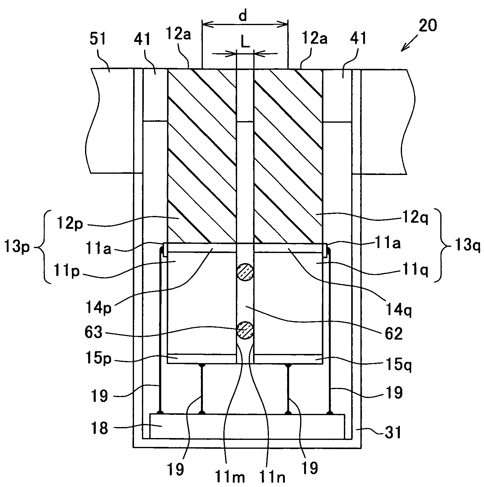
[0065]The ultrasonic sensor 20 according to the second embodiment has similar effects as the ultrasonic sensor 10 according to the first embodiment has. In addition, the ultrasonic sensor 20 according to the second embodiment has the following effects. According to the second embodiment, the spacer 63 is embedded into the bonding member 62. The spacer 63 has an exterior size approximately equal to a thickness of the bonding member 62. An elastic modulus of the spacer 63 is larger than that of the bonding member 62. The spacer 63 and the bonding member 62 are integrally formed. Since the spacer 63 contacts the side surface 11m of the piezoelectric element 11p and the side surface 11n of the piezoelectric element 11q, it is possible to maintain the space interval between the side surface 11m of the piezoelectric element 11p and the side surface 11n of the piezoelectric element 11q at a given distance while a combination of the spacer 63 and the bonding membe...

third embodiment

Effect of Third Embodiment

[0077]The bonding member 64 includes the bonding layers 65 for fixing the piezoelectric elements 11p to 11s and the core member 66 located between the bonding layers 65. The core member 66 has a plate shape and made of hard resin. Accordingly, the shape of the bonding member 64 is easily maintained. The bonding member 64 is easy to use in a bonding process. Since the acoustic impedance of the bonding layer 65 is different from that of the core member 66, the vibrations trying to conduct between the piezoelectric elements 11p to 11s are reflected at a boundary between the bonding layer 65 and the core member 66. Thus, vibration conduction between the piezoelectric elements 11p to 11s is suppressed. Therefore, it is possible to provide a favorable cross talk characteristic.

[0078]The bonding layers 65 include the line 65a for connecting between each piezoelectric element 11p to 11s and an external line. Thus, it is possible to electrically connect between each...


PUM


Abstract

An ultrasonic sensor is disclosed. The ultrasonic sensor includes a plurality of sensor elements arranged in an array. Each sensor element includes an ultrasonic sensing element and an acoustic matching member. The ultrasonic sensor further includes a bonding member having a thickness approximately equal to a space interval between adjacent ultrasonic sensing elements. The bonding member adhesively fixes the plurality of sensor elements, and includes a portion contacting each ultrasonic sensing element. An elastic modulus of the portion is smaller than that of each ultrasonic sensing element.

Description

CROSS REFERENCE TO RELATED APPLICATION[0001]The present application is based on Japanese Patent Application No. 2007-254666 filed on Sep. 28 2007, the disclosure of which is incorporated herein by reference.BACKGROUND OF THE INVENTION[0002]1. Field of the Invention[0003]The present invention relates to an ultrasonic sensor including multiple sensor elements arranged in an array.[0004]2. Description of Related Art[0005]An ultrasonic sensor that has multiple sensor elements arranged in an array has been known. Such an ultrasonic sensor is used for measuring a location of an obstacle existing forward of the ultrasonic sensor, and used for sensing a shape of the obstacle. Also, an ultrasonic transducer for obtaining an ultrasound image has been known in, for example, a medical field. When this type of an ultrasonic sensor measures a location and a shape of an obstacle, it is typically required to obtain a time interval between transmission and reception of the ultrasonic wave. Further, ...

Claims


Application Information

Patent Timeline
Patent Type & Authority Patents(United States)
IPC IPC(8): H01L41/08B60R21/00G01S7/521G01S15/931H04R17/00
CPCG01S7/521H04R17/02G01S15/931
Inventor OKUDA, YASUYUKISUGIURA, MAKIKO
Owner DENSO CORP
Why Eureka
Try Eureka