Image forming apparatus with a toner image density feature and related method

a technology of density feature and image, applied in the field can solve the problems of difficult frequent control of image forming apparatus, inability to respond to characteristics, and density variation of images, and achieve the effects of reducing image forming productivity, excellent image formation, and reducing density and tonality variations

Inactive Publication Date: 2010-05-11
CANON KK
View PDF14 Cites 4 Cited by
  • Summary
  • Abstract
  • Description
  • Claims
  • Application Information

AI Technical Summary

Benefits of technology

[0014]It is an object of the present invention to provide an image forming apparatus capable of performing excellent image formation with smaller density and tonality variations at all times without causing a reduction in productivity of image formation and extra consumption of developer.

Problems solved by technology

In the above-mentioned image forming method, however, the density may vary from image to image, because the image forming apparatus may not be able to respond to characteristics constantly varying due to long hours of image formation in the course of a day's work, such as changes in dark / light potential parts of the image bearing body or photosensitive drum, and changes in the amount of charge of developer.
In addition, since time-consuming and troublesome work is required for the above-mentioned pre-rotational image control, it is difficult to frequently carry out this control.
However, since the post-rotational image control is performed after image formation on a predetermined number of sheets, no image cannot be formed during the control period, reducing user productivity.
On the other hand, since the inter-sheet image control method forms patches between printing sheets, it requires a longer time to perform the control at an interval between printing sheets, causing a reduction in the number of formed images producible at the same processing rate.
In both of the foregoing image control methods, the image patterns are formed as patches other than images desired by the user to be formed in the image forming process, causing extra consumption of developer and promotion of contamination in the image forming apparatus.

Method used


Image

  • Image forming apparatus with a toner image density feature and related method
  • Image forming apparatus with a toner image density feature and related method
  • Image forming apparatus with a toner image density feature and related method

Examples


first embodiment

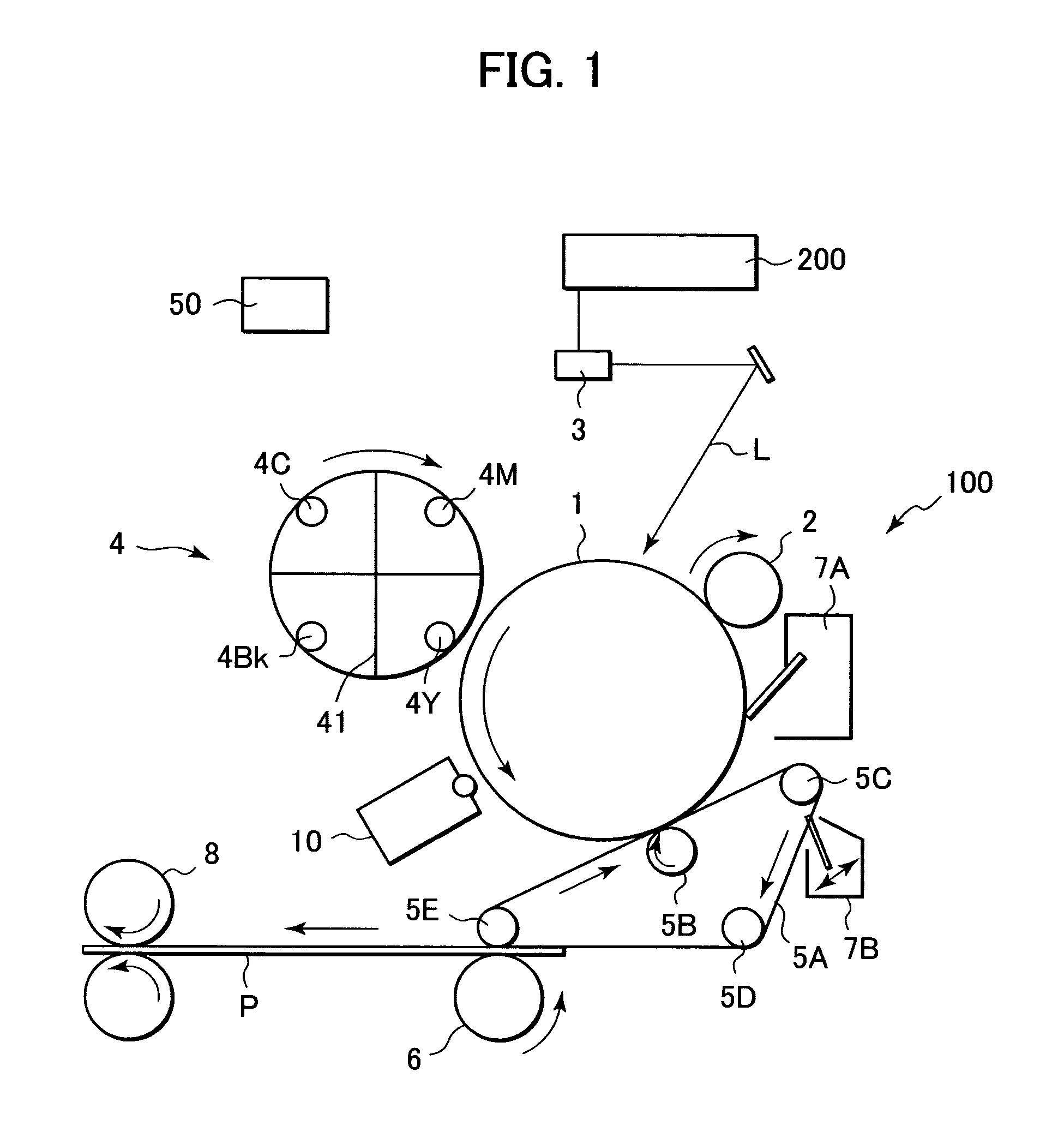
[0036]FIG. 1 shows a full-color printer as the image forming apparatus according to a first embodiment of the present invention.

[0037]An image forming apparatus 100 is either connected to or integrated with a reader part 200. The reader part 200 is a device for converting outside information into an image signal, such as an imaging apparatus for reading images of an original from the outside or a personal computer. For example, a luminance signal from the original image read by the imaging apparatus or an image signal transferred from the personal computer is sent to the image forming apparatus 100.

[0038]A full-color printer (hereinafter called the “printer”) 100 as the image forming apparatus 100 shown in FIG. 1 is equipped with a photosensitive drum 1 as an image bearing body, and operates the photosensitive drum 1 to form an image (toner image) developed with developer on the drum 1 based on image information from the reader part 200 according to an image forming process basicall...

second embodiment

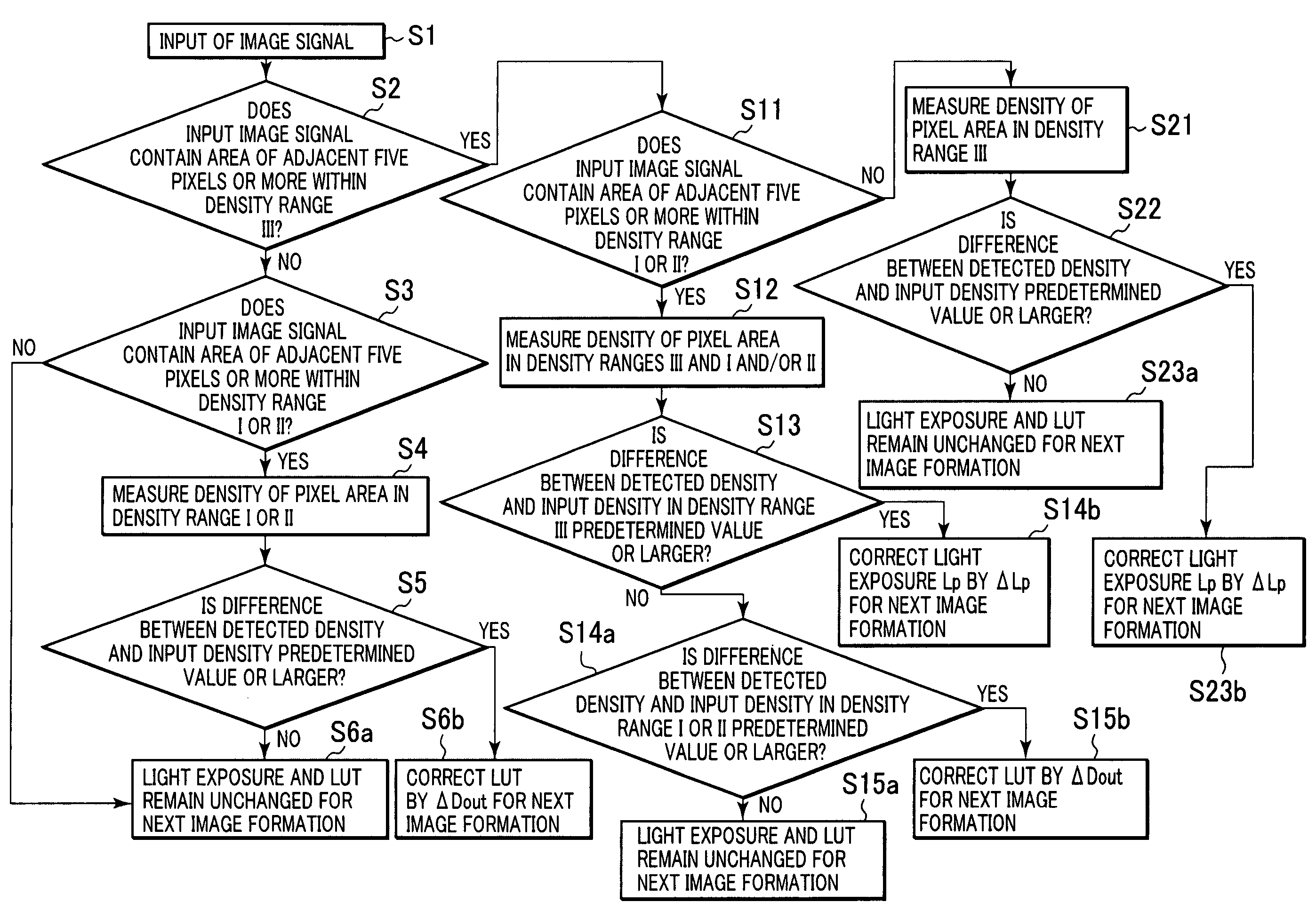
[0114]In the first embodiment, the control is made by correcting only the LUT. However, there is a case where correction is not possible for a certain density range.

[0115]Specifically, when a density drop in the high-density range III of 1.6 to 1.8 occurs in the image forming apparatus, for example, due to a radical change in environment, temperature or humidity during image formation in the course of a day's work, light potential V1 may increase over a predetermined width or more or the amount of charge of developer may go too high. In such a case, a 255-level output image signal Dout may not be able to be outputted at the maximum density of 1.8.

[0116]Therefore, in this embodiment, image formation is performed by changing control conditions according to the density range. Specifically, the amount of exposure from the exposure means is changed in the density range III of 1.6 to 1.8, while the LUT is corrected in the density ranges I and II in the same manner as the first embodiment....


PUM


Abstract

An image forming apparatus includes an image forming part for forming a toner image on an image bearing body based on an image signal, and a density detection part for detecting a density of the toner image on the image bearing body, such that it is determined whether a normal image formed by the image forming part has a density detection area which should be detected, and if it is determined that the density detection area is present, image forming conditions are controlled based on a detection result of the density detection area.

Description

BACKGROUND OF THE INVENTION[0001]1. Field of the Invention[0002]The present invention relates to an image forming apparatus, such as a copying machine, a printer, or a facsimile, for forming images according to an image forming process using an electrophotographic system or an electrostatic recording system.[0003]2. Description of the Related Art[0004]Conventionally, it has been desired that an image forming apparatus such as a copying machine or printer using an electrophotographic system should reproduce images from the same image data on a transfer material at a constant density.[0005]To this end, the image forming apparatus forms a specific pattern of developed images (patches) for density detection on an image bearing body such as a photosensitive drum at a preliminary stage prior to the image forming process, that is, during a pre-rotation period upon completion of warm-up operation after startup. The image forming apparatus then reads out the density of the formed pattern, an...

Claims


Application Information

Patent Timeline
Patent Type & Authority Patents(United States)
IPC IPC(8): G03G15/00G03G15/02G03G15/043G03G15/10G03G15/08
CPCG03G15/5041G03G2215/00042G03G2215/0005
Inventor YAMAMOTO, TAKEO
Owner CANON KK
Why Eureka
Try Eureka