
Method for controlling a fuel mixture for an internal combustion engine and corresponding control unit

Inactive Publication Date: 2010-05-18
VITESCO TECH GMBH
View PDF8 Cites 0 Cited by
  • Summary
  • Abstract
  • Description
  • Claims
  • Application Information

AI Technical Summary

Benefits of technology

[0005]An object of the invention is to provide a method of mixture control which reliably ensures high conversion quality even with reduced size catalytic converters.
[0007]With the method according to the invention, a control unit successively reads in the lambda values measured by the lambda probe and compares the current lambda value with a previously read-in lambda value. If the comparison indicates a fall in the lambda value, the control unit can initiate a mixture change. This mixture change is initiated if the lambda value has fallen by or by more than a predefined constant. To this end the change in the lambda value is compared with the constant. A lambda value falling by more than a predefined constant indicates that catalytic converter breakdown is imminent, and so direct intervention in the formation of the mixture takes place via the control unit. On the other hand, if the lambda value falls by less than the predefined constant, the control unit initiates a check to ascertain whether the lambda value continues to fall for a number of subsequent measured values. In this checking mode, also known as dynamic mode, intervention in the mixture formation process does not therefore takes place immediately. This method allows unnecessary interventions in mixture formation to be reduced, thereby making it possible for the size of the catalytic converter to be reduced while at the same time ensuring reliable exhaust gas conversion.

Problems solved by technology

To improve exhaust gas conversion still further, efforts are made to reduce the size of the catalytic converter, as although a large catalytic converter allows good buffering of mixture faults, it requires a large amount of energy in the heating-up phase and exhibits poor starting behavior.

Method used


Image

  • Method for controlling a fuel mixture for an internal combustion engine and corresponding control unit
  • Method for controlling a fuel mixture for an internal combustion engine and corresponding control unit
  • Method for controlling a fuel mixture for an internal combustion engine and corresponding control unit

Examples


Embodiment Construction

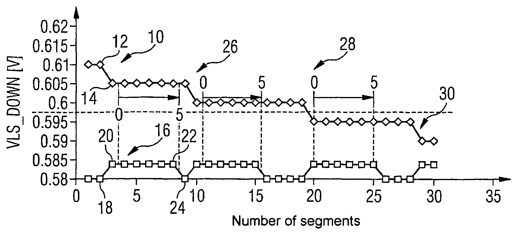
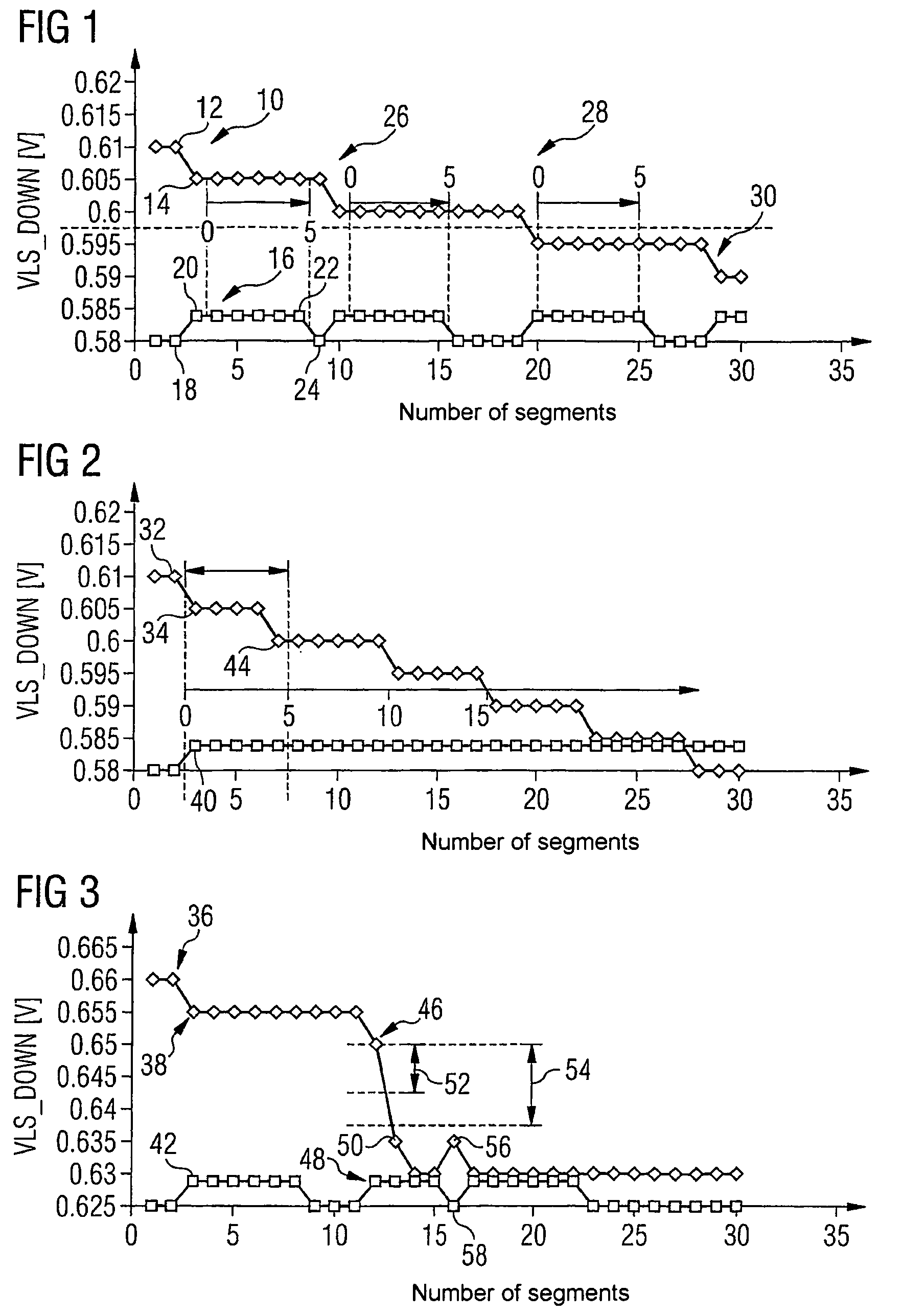
[0017]FIG. 1 shows the sequence of the post-cat signals 10 over the number of segments. The post-cat sensor is a binary sensor whose signals are analyzed in the transition range of rich and lean mixture formation. The measured post-cat signal VLS_DOWN is set in relation with two operating point dependent maximum and minimum values. The maximum value VLS_DOWN_MAX and the minimum value VL_DOWN_MIN preferably depend on the current mass air flow (MAF) and the engine speed (N). Using the minimum and maximum value, a reference value FAC_VLS_DOWN is determined. The reference value is calculated according to the following formula:

[0018]FAC_VLS⁢_DOWN=VLS_DOWN-VLS_DOWN⁢_MINVLS_DOWN⁢_MAX-VLS_DOWN⁢_MIN

The reference value assumes values less than 0 when VLS_DOWN is less than VLS_DOWN_MIN. If the current lambda value is greater than the maximum value (VLS—DOWN>VLS_DOWN_MAX), values greater than 1 may also occur.

[0019]In the course of the method it is established whether a falling VLS_DOWN sign...


PUM


Abstract

The invention relates to a method for regulating the mixture in an internal combustion engine by means of a catalytic converter and a lambda probe that is placed downstream of the catalytic converter. Depending on the historical signal values, said method determines whether intervention in the formation of the mixture is required, whether the existing signal is only decreasing slowly, which necessitates slow regulatory intervention, or whether the signal of the probe placed downstream of the catalytic converter decreases rapidly, which necessitates rapid regulatory intervention. The difference types of intervention enable the volume of the catalytic converter to be reduced, thus preventing high consumption in the warm-up phase or the poor start-up behavior of large catalytic converters.

Description

CROSS REFERENCE TO RELATED APPLICATIONS[0001]This application is the U.S. National Stage of International Application No. PCT / EP2004 / 052012, filed Sep. 2, 2004 and claims the benefit thereof. The International Application claims the Benefits of German application No. 10340815.0, filed Sep. 4, 2003. The International Application and the German application are incorporated by reference herein in their entirety.FIELD OF THE INVENTION[0002]The present invention relates to a method for mixture control in an internal combustion engine with a catalytic converter and a lambda probe downstream of said catalytic converter.BACKGROUND OF THE INVENTION[0003]DE 102 06 399 C1 discloses a method for forced activation of a lambda control system which improves exhaust gas conversion in the case of a three-way catalytic converter, wherein mixture control having alternately rich and lean exhaust gas packets is performed varyingly around a lambda setpoint value. For particularly reliable exhaust gas con...

Claims


Application Information

Patent Timeline
IPC IPC(8): F01N3/00F02D41/14
CPCF02D41/1439F02D41/1454
Inventor ELLMER, DIETMARLAUER, THORSTEN
Owner VITESCO TECH GMBH
Learn More