Composite hose with corrugated metal tube
a technology of corrugated metal and composite hoses, which is applied in the direction of flexible pipes, hose connections, mechanical equipment, etc., can solve the problems of difficult to ensure sufficient sealing properties between the insert pipe, and difficult to satisfy the future requirements of hoses made only of organic materials, so as to achieve the effect of enhancing the life of the composite hose with the corrugated metal tub
Inactive Publication Date: 2010-05-18
SUMITOMO RIKO CO LTD
View PDF13 Cites 11 Cited by
- Summary
- Abstract
- Description
- Claims
- Application Information
AI Technical Summary
Benefits of technology
The design effectively prevents axial fractures and enhances the durable life of the composite hose by ensuring a secure seal and reducing metal fatigue, allowing for repeated internal pressure cycles without failure.
Problems solved by technology
Then it is anticipated difficult to satisfy the future requirements with hoses made only of organic materials such as rubber or resin.
However, as an inner layer, i.e., a corrugated metal tube in the hose with the corrugated metal tube is difficult to deform, if the hose with corrugated metal tube is adapted, it will be a problem how to construct fastening structure on an end portion of the hose with the corrugated metal tube so as to assure sealing property thereon.
However, in the composite hose with the corrugated metal tube, it is hard to bring about a sufficient bonding strength between the corrugated metal tube and the insert pipe.
When a seal is provided only by fitting relation between the inner circumferential surface of the corrugated metal tube and the outer circumferential surface of the insert pipe, it is difficult to ensure sufficient sealing property therebetween.
However, later on, a problem is found that a durability or durable life of the straight-walled portion 214 is not sufficient in the composite hose with the corrugated metal tube.
Specifically, a durability test was conducted with the composite hose with the corrugated metal tube by exerting an internal pressure to the composite hose repeatedly, and the problem is found that an axial fracture or axial crack was caused on a part of the straight-walled portion 214.
This region with the wave pattern is vulnerable to a load or pressure from the internal fluid.
Then, it is estimated that large local distortion and elongation is caused in the region, and finally, a fracture or crack propagates through the region in the axial direction due to metal fatigue.
That problem is found later on.
Method used
View moreImage
Smart ImageViewing Examples
Examples
example 1
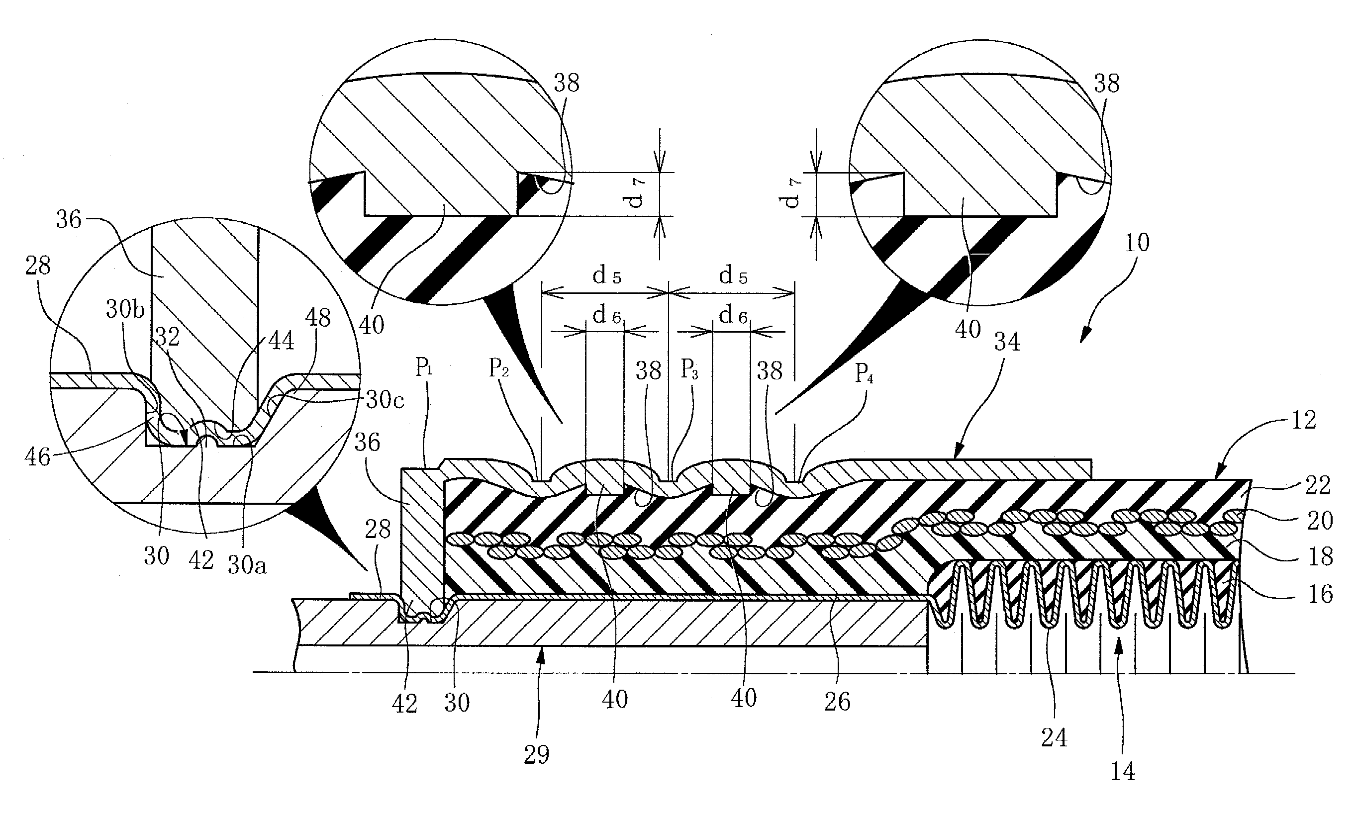
[0137 includes the socket fitting 34 that is provided with the above holddown portion 40 on an inner circumferential surface thereof, while Example 2 includes a socket fitting that is not provided with the holddown portion 40.
Login to View More PUM
| Property | Measurement | Unit |
|---|---|---|
| inner diameter | aaaaa | aaaaa |
| taper angle | aaaaa | aaaaa |
| taper length | aaaaa | aaaaa |
Abstract
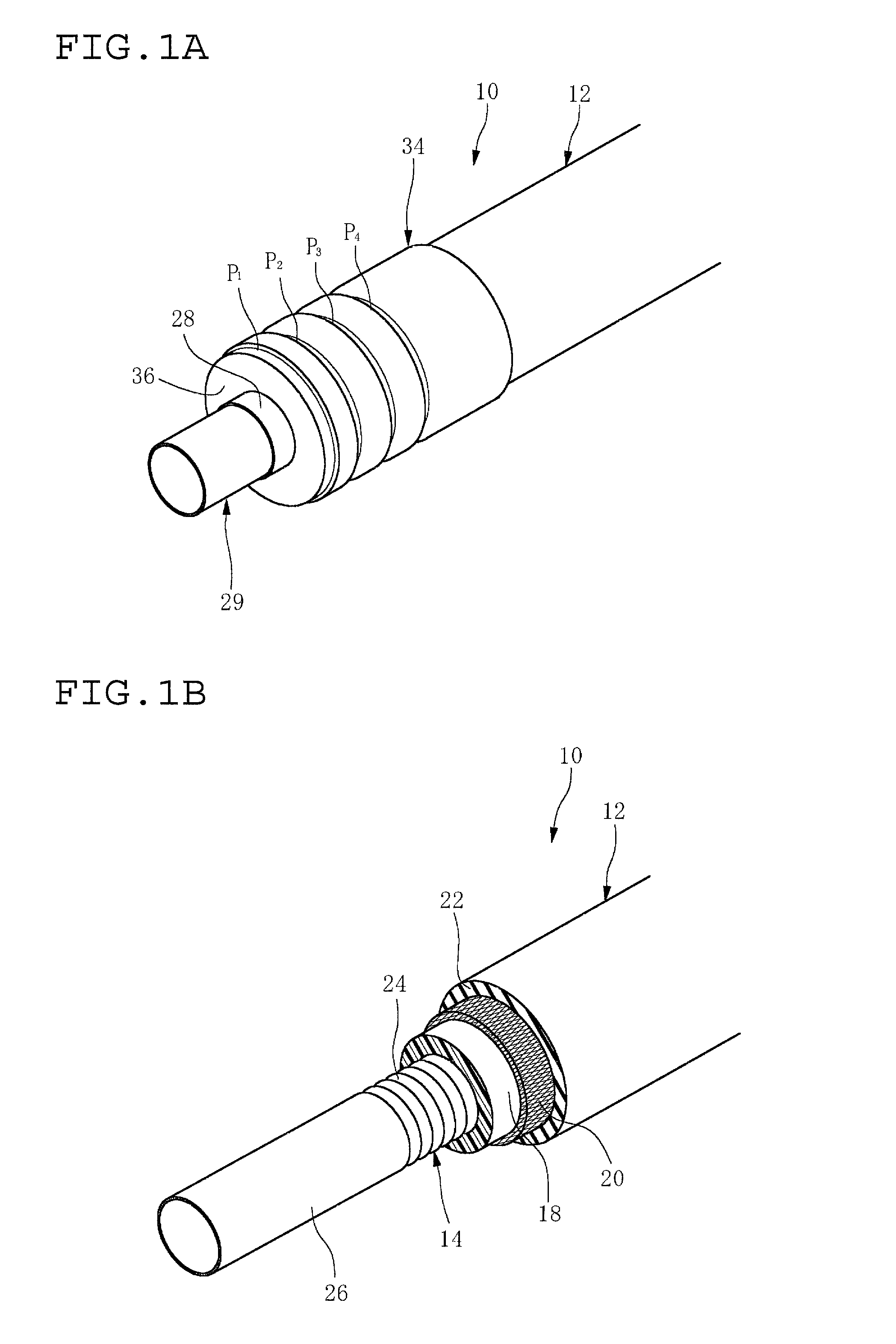
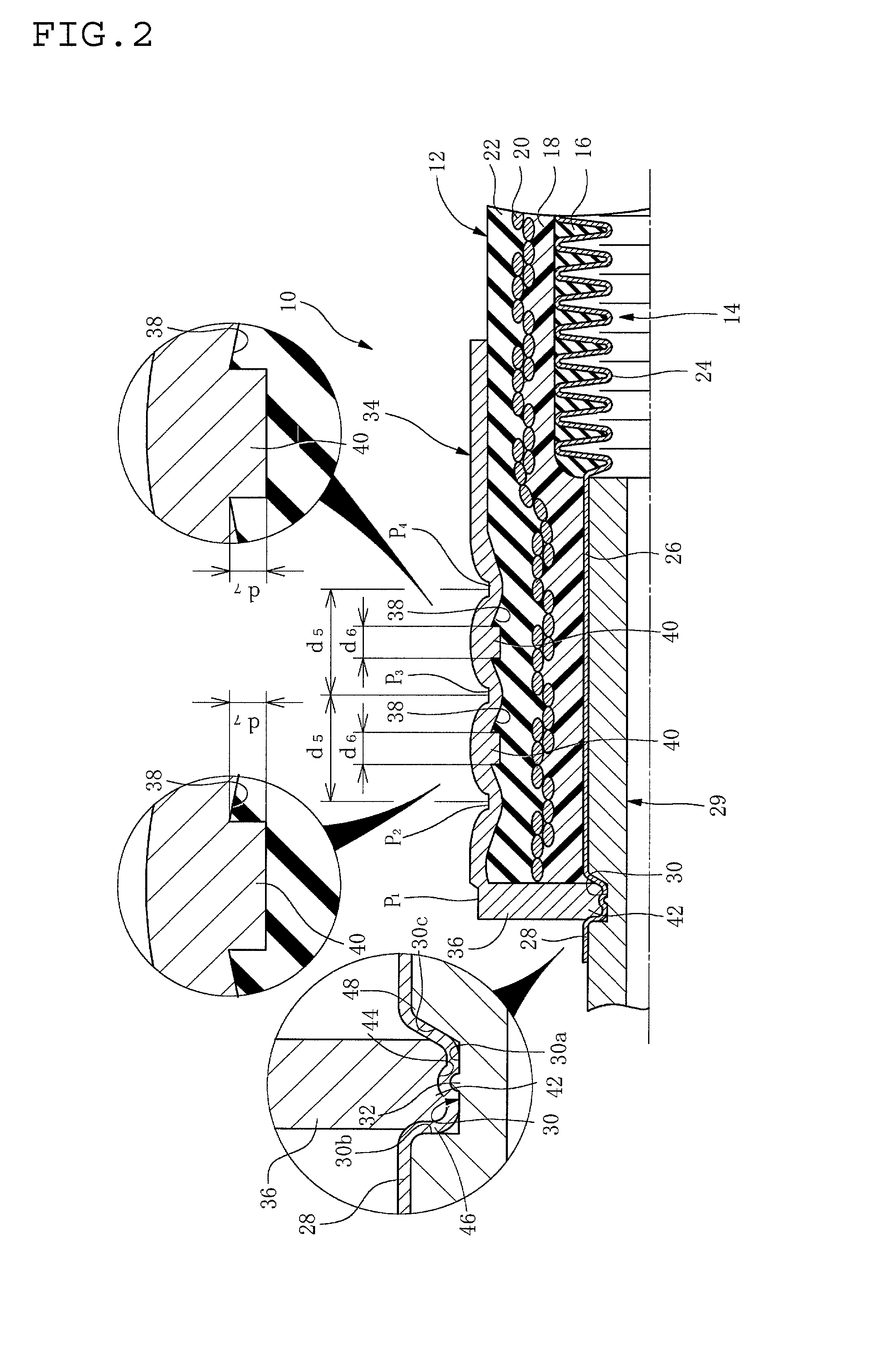
A composite hose with a corrugated metal tube has a hose body having a corrugated metal tube and an outer layer. The corrugated metal tube includes a non-corrugated straight-walled portion on an end portion thereof, and a rigid insert pipe is inserted in the straight-walled portion. A socket fitting is fitted on the hose body by being swaged thereon radially inwardly, and an inner circumferential end portion of the collar portion and an outer circumferential surface of the insert pipe compress an extending portion of the straight-walled portion to fix the straight-walled portion onto the insert pipe and provide a seal between the outer circumferential surface of the insert pipe and an inner circumferential surface of the straight-walled portion. A fracture preventing mechanism is provided on a hose end portion for preventing fracture of the straight-walled portion.
Description
BACKGROUND OF THE INVENTION[0001]1. Field of the Invention[0002]The present invention relates to a composite hose with a corrugated metal tube, which is suitable for a fuel transporting hose for a motor vehicle or a hose transporting fluid such as refrigerant, and more particularly to a composite hose with a corrugated metal tube having a specific fastening structure on an end portion thereof.[0003]2. Description of the Related Art[0004]Typical rubber hoses, for example, made of blended product of acrylonitrile-butadiene rubber and polyvinyl chloride (NBR / PVC blend) that is excellent in a gasoline permeation resistance, have been used for conveying fuel for automobiles or the like in view of their high vibration-absorbability, easiness of assembly or the like. However, for the purpose of global environment protection, the regulations have been recently tighten against permeation of a fuel for motor vehicles or the like, and are anticipated to be further tightened in the future. Furt...
Claims
Login to View More Application Information
Patent Timeline
 Patent Type & Authority Patents(United States)
IPC IPC(8): F16L11/00
CPCF16L11/085F16L33/2076F16L11/11
Inventor TAKAGI, YUJI
Owner SUMITOMO RIKO CO LTD
Features
- R&D
- Intellectual Property
- Life Sciences
- Materials
- Tech Scout
- Unparalleled Data Quality
- Higher Quality Content
- 60% Fewer Hallucinations
Learn More Browse by: Latest US Patents, China's latest patents, Technical Efficacy Thesaurus, Application Domain, Technology Topic, Popular Technical Reports.
© 2025 PatSnap. All rights reserved.Legal|Privacy policy|Modern Slavery Act Transparency Statement|Sitemap|About US| Contact US: help@patsnap.com


