
Snap lock separatory panel and retainer system

a technology of retainer and separator, which is applied in the direction of solid separation, fastening means, screws, etc., can solve the problems of increasing the time required to install the system and replace worn screen panels, and the provision of screen panel edge strips which are less easily installed than would be desired, so as to achieve easy use and reduce the time required for assembling and removing

Active Publication Date: 2010-05-18
CONN WELD IND
View PDF17 Cites 17 Cited by
  • Summary
  • Abstract
  • Description
  • Claims
  • Application Information

AI Technical Summary

Benefits of technology

The system ensures secure retention of separatory panels, minimizes downtime, and adapts to dimensional variations, allowing for quick installation and maintenance without modifying the underlying machinery, thus reducing production losses and extending equipment lifespan.

Problems solved by technology

While the screen panel retainer system described in the Bacho et al. patent has found acceptance in the industry because it does not require modification, or re-working of the industry standard screen stringer rails, it has been found to be somewhat difficult to use and has required the provision of screen panel edge strips which have been less easily installed than would be desired.
This alignment and abutment has been somewhat difficult to obtain in the field and has increased the time that has been required to initially install the system and to then replace worn screen panels with replacement screen panels.
In an industrial setting, the amount of time that is required for a machine to be out of service, for repair or refurbishment results in a loss of production capability.
In the screen panel retainer system described in the Bacho et al. patent, these times were not able to be minimized to the hoped for degree.
Over the course of time, the slurry abrades the holes and causes them to enlarge.
Since a number of the currently available panel retainer systems utilize some type of an interference fit of pins, pegs or the like into these holes, the enlargement of these holes is problematic.
At some point, the stringer rail holes become so enlarged that they will no longer engage the pins or pegs with sufficient retentive force.
In each such instance, the process involves considerable work and the equipment being taken out of service.

Method used


Image

  • Snap lock separatory panel and retainer system
  • Snap lock separatory panel and retainer system
  • Snap lock separatory panel and retainer system

Examples


first embodiment

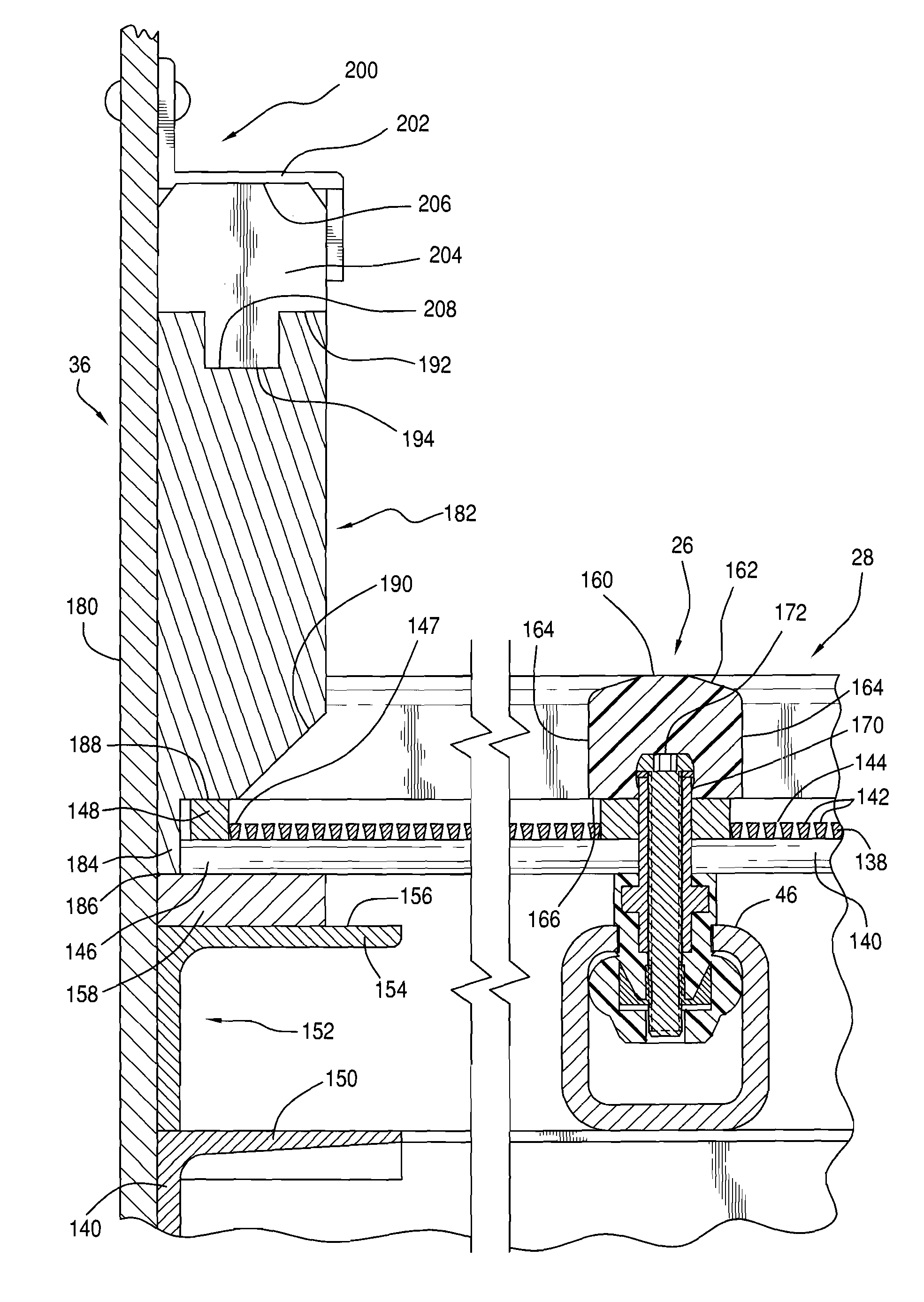
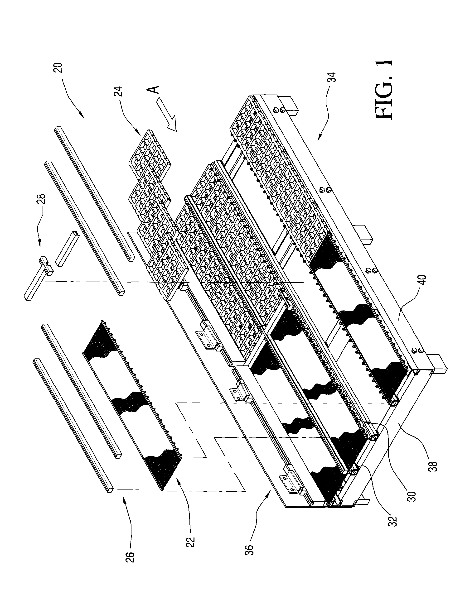
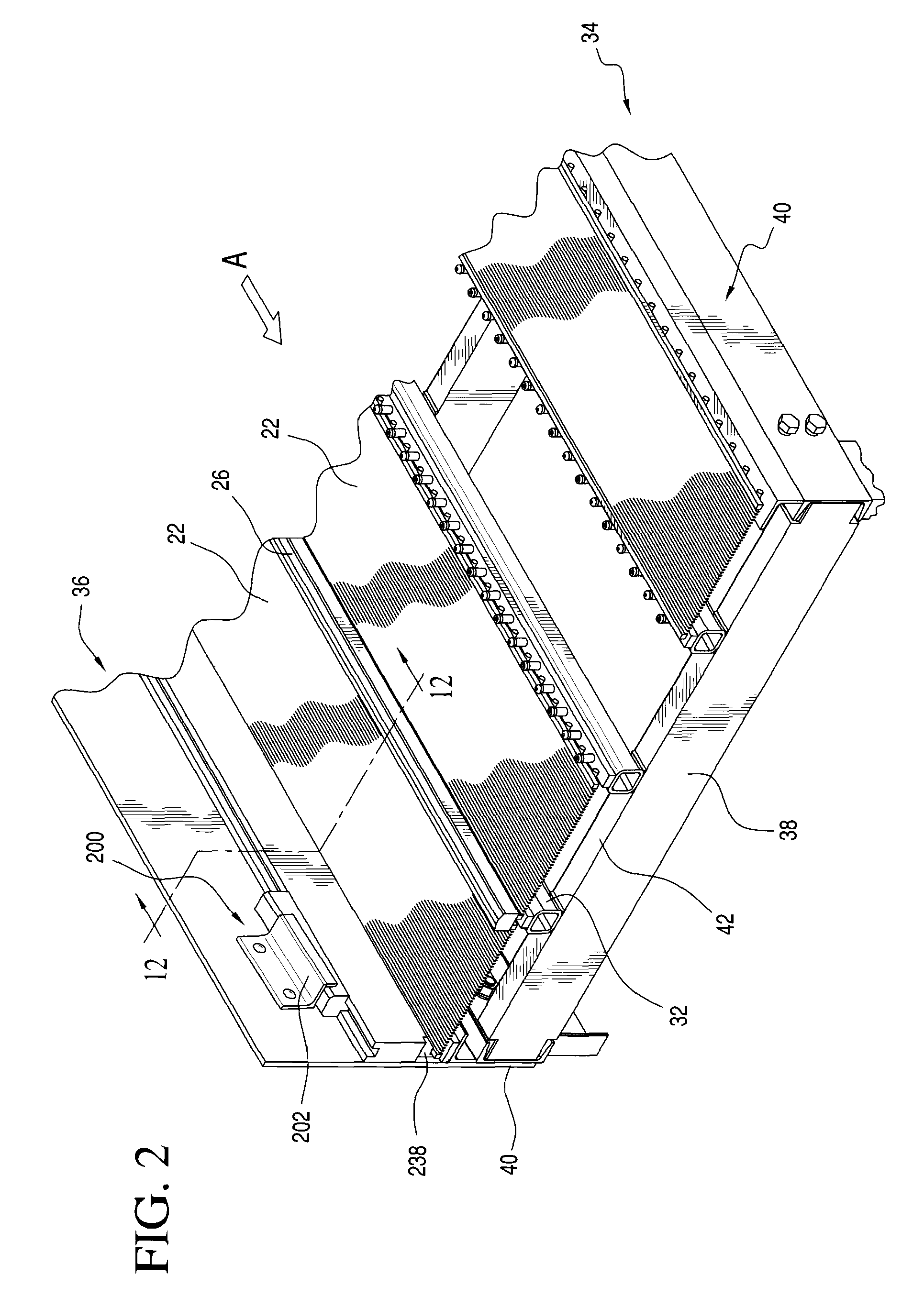
[0051]Referring again to FIG. 7, and as may also be seen in more detail in FIG. 9, in a first preferred embodiment of the present invention, each center retainer 30 is an elongated bar 50 and including a plurality of spaced, upwardly projecting center retainer pins, generally at 52. Each such center retainer pin 52 includes a pin shank 54 and an enlarged pin retainer head 56. In the center retainer, generally at 30, as depicted in FIG. 9, the center retainer pins, generally at 52 are constituted by simple retainer pins 58 and by compound retainer pins 60. While all of the retainer pins cooperate with the locking strips 26, as will be discussed in detail shortly, the compound retainer pins 60 also act to secure the center retainers 30 to the screen stringer rails 32.

[0052]As may be seen most clearly in FIG. 9, in its first preferred embodiment, the center retainer 30 includes a central, generally rectangular retainer spine 62 of metal or another suitable material. Such a central reta...

second embodiment

[0068]In the sidewall assembly shown in FIG. 20, the profile strip 212 is placed on the outboard edge of the outermost screen wire panel 22 before that screen wire panel is installed. Once the profile strip 212 has been so placed, the screen wire panel 22 can be installed and the sideboard 220 can be wedged in place. This positive securement will retain the outboard ends of the outer screen panels firmly in place.

[0069]After the various screen wire panels 22 have been positioned on the screen stringer rails 32 and on the screen stringer angle irons 152, the locking strips 26 are installed. As discussed previously, these locking strips 26 overlie the center retainer 32 and are held in place by the cooperative engagement of the enlarged heads 56 of the simple retainer pins 58 and of the compound retainer pins 60 in the cooperatively shaped receptacles 172 that are formed in each locking strip 26. As discussed previously, the sizes and dimensions of the pin shanks, the pin heads, the d...


PUM


Abstract

A snap lock separatory panel and retainer system includes either a screen wire panel with laterally spaced, longitudinally extending locking bars defining a locking profile, or a urethane panel with laterally spaced, longitudinally extending lips or flanges which also define a locking profile. A retainer system is provided for use in securing these panels. The retainer system utilized center retainers that are engagable with industry standard holes in screen stringer rails of a vibrating separating machine. Each center retainer is provided with an array of retainer pins which are spaced to interdigitate with either screen wire tie rod ends or with urethane panel wall recesses to support the screen panel locking bars or the urethane panel flanges adjacent the retainer pins. Locking strips are provided with undercurrent bores that terminate in undercut receptacles. These bores and receptacles are sized to receive center retainer pin shanks and heads. The locking strips and center retainers cooperate to positively secure the snap lock screen wire panels and / or urethane panels in place on a vibrating separatory machine.

Description

FIELD OF THE INVENTION[0001]The present invention is directed generally to a snap lock separatory panel retainer system and to a separatory panel which is usable with such a retainer system. More particularly, the present invention is directed to a separatory panel retainer system that retains separatory panels in a vibrating separatory machine. Most specifically, the present invention is directed to a separatory panel retainer system that utilizes elongated locking strips which engage locking profiles on separatory panels in the vibrating separatory device. These locking strips utilize undercut receptacles to receive enlarged heads of retainer pins that are formed integrally with center retainer strips. The center retainer strips are, in turn secured to screen stringer rails that are typically provided in vibrating separating machines. The locking strips are snap locked onto the center retainer by the engagement of the enlarged heads of the retainer pin in the cooperatively shaped ...

Claims


Application Information

Patent Timeline
Patent Type & Authority Patents(United States)
IPC IPC(8): B07B1/49
CPCB07B1/46F16B29/00B07B1/4645
Inventor BACHO, FRANK J.LANE, TRACY LEONARD
Owner CONN WELD IND
Learn More