Slide rail unit

a technology of sliding rail and slide rail, which is applied in the direction of safety belts, movable seats, pedestrian/occupant safety arrangements, etc., can solve the problems of small errors generated during processing of component parts, slide rail units failing to exhibit the desired design strength as a whole, and insufficient slide restraints on rails, so as to achieve reliable completion, prevent displacement, and increase productivity

Active Publication Date: 2010-05-18
IMASEN ELECTRIC IND
View PDF10 Cites 26 Cited by
  • Summary
  • Abstract
  • Description
  • Claims
  • Application Information

AI Technical Summary

Benefits of technology

[0011]Therefore, it is an object of the invention to provide a slide rail unit which is simple and compact in structure and easy to assemble and, even when right and left rails are installed to a vehicle floor at an inclination angle different from each other with respect to the longitudinal direction thereof, the right and left rails reliably perform the slide restraint.
[0023]Further, in the slide rail unit of the first aspect of the invention, the leaf spring member disposed between the operation lever and the lock lever includes the first nip-holding portion and the second nip-holding portion as well as the first engagement portion and the second engagement portion. The first nip-holding portion and the first engagement portion are connected to the lock lever. The first nip-holding portion holds the end portion of the lock lever, and the first engagement portion engages therewith in an anti-disengagement manner. On the other hand, the second nip-holding portion and the second engagement portion are connected to the operation lever. The second nip-holding portion holds the end portion of the operation lever, and the second engagement portion engages therewith in an anti-disengagement manner. That is, the leaf spring member is connected to the lock lever and the operation lever through a process of hold and engagement. Therefore, so-called one-touch connection is achieved, and also the displacement is reliably prevented after the connection. Therefore, in the slide rail unit of the first aspect of the invention, after connecting one end of the leaf spring member to the lock lever (or operation lever), only by push the other end of the leaf spring member onto the operation lever (or lock lever), the connecting is reliably completed. Consequently, the assembly work of the slide rail unit is facilitated resulted in an increase of the productivity and a reduction of the manufacturing cost.
[0024]In the slide rail unit of the second aspect of the invention includes the pair (right and left) of slide rail members. Both end portions of the operation lever, which are inserted from one end portion of the slide rail members, are connected to the lock levers within the slide rail members. Between the operation lever and the respective lock levers, the leaf spring members are disposed, and the leaf spring member imparts a force to the operation lever and the lock lever in a direction to pull the both closer to each other. Therefore, when a load is applied to the operation lever in a direction opposite to the force imparted by the leaf spring member, a force acts on the operation lever to pull back the same toward the lock lever. Therefore, when the pair (right and left) of slide rail members including therein the lock levers connected to the operation lever as described above is installed to a vehicle floor at an inclination angle different from each other with respect to the longitudinal direction thereof, the operation lever tends to part away from the lock lever against the force imparted by the leaf spring member. However, the leaf spring member pulls the operation lever and the lock lever in a direction closer to each other, and thus the connection therebetween is maintained. Therefore, according to the invention of the second aspect, the operation lever and the lock lever are permitted to part away a little from each other while maintaining the state that both are held close to each other. Therefore, even when an error is generated in installation angle between the right and left slide rail members, the error can be absorbed. Therefore, since an unintended force is prevented from being given to one or both of the slide rail members by the operation lever, slide restraint can be reliably achieved with the right and left seat rail members. It should be noted that, according to the second aspect of the invention, an error of installation angle due to deformation of the floor generated at vehicle collision can be also absorbed, and thus the slide restraint can be reliably achieved.
[0026]Therefore, according to the third aspect of the invention, the lock lever is supported at two points by the first nip-holding portion and the first engagement portion. On the other hand, the operation lever is supported at two points by the second nip-holding portion and the second engagement portion. Consequently, the leaf spring member can be connected strongly and stably to the lock lever and the operation lever. Further, according to the third aspect of the invention, since the structure is simple, the leaf spring member can be manufactured easily, and the risk of failure of the slide rail unit can be reduced.
[0027]Furthermore, in the leaf spring member according to the fourth aspect of the invention, both of the end portions to be connected to the lock lever or the operation lever are formed in a configuration identical to each other. Either side of the leaf spring member can be connected to either of the lock lever and operation lever. Therefore, the slide rail unit can be manufactured more easily resulting in an increase of the productivity moreover.
[0028]According to the fifth to eighth aspects of the invention, either one or both of the operation lever and the lock lever are formed with a projection that causes the operation lever and the lock lever to engage with each other. Therefore, when a passenger operates the operation lever at least in a direction to release the slide restraint, the operation lever and the lock lever come into contact with the projection and the leaf spring member at two points. Thus, utilizing the principle of leverage, the lock lever can be reliably rotated in the direction to release the slide restraint.

Problems solved by technology

However, there is a possibility that a small error may be generated during processing the component parts of the slide rail units, mounting the slide rail units onto a vehicle seat and / or attaching the vehicle seat to the vehicle floor.
When such error is generated, each of the right and left rails may be installed at an inclination angle different from each other.
Under such circumstances, if the right and left rails are installed at an inclination angle different from each other with respect to a longitudinal direction thereof, one end of the operation lever may give an unintended force to a lock mechanism on a rail resulting in an insufficient slide restraint on the rail.
As a result, there may arise such a problem that slide rail units fail to exhibit desired design strength as a whole.
Such problem of cantilever may occur when a vehicle mounted with the slide rail units collides.
Therefore, the slide rail cannot be constructed in a compact size resulting in a large size of the slide rail unit itself.
Even when the lock mechanism is disposed within the rail to reduce the size, since a torsion spring (18) has to be hooked to an elongated hole (17b), the assembling work thereof becomes extremely difficult due to the structure thereof.
Consequently, it is difficult to provide the slide rail unit with a compact structure.
Therefore, there is such a problem that the attaching work is difficult to carry out due to the structure.
Therefore, there is a problem that the assembly work of the slide rail unit is complicated.

Method used


Image

  • Slide rail unit
  • Slide rail unit
  • Slide rail unit

Examples


example

[0043]A particularly preferable example of the above-described embodiments will be described below.

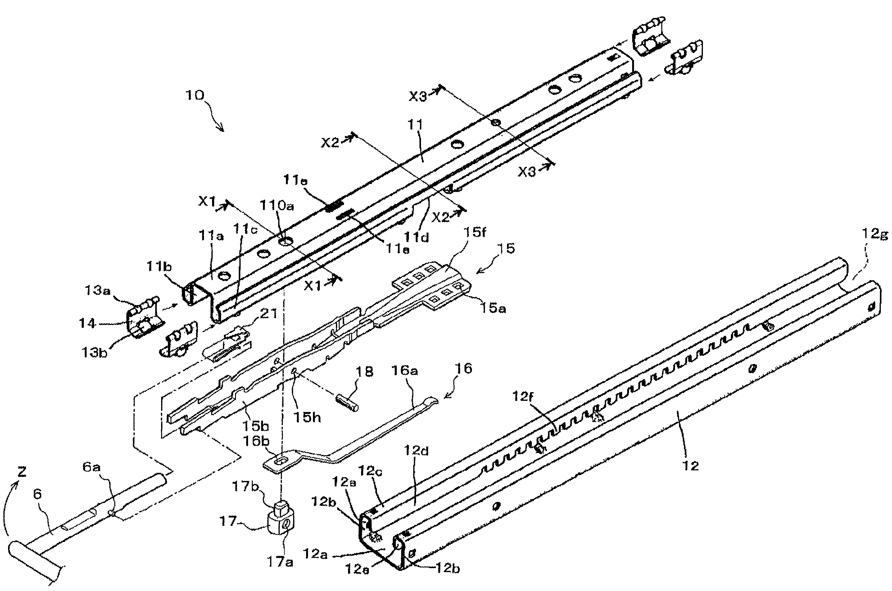
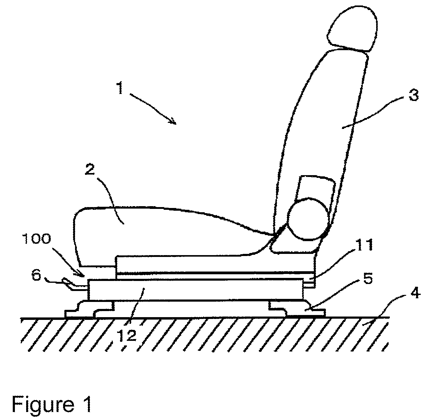
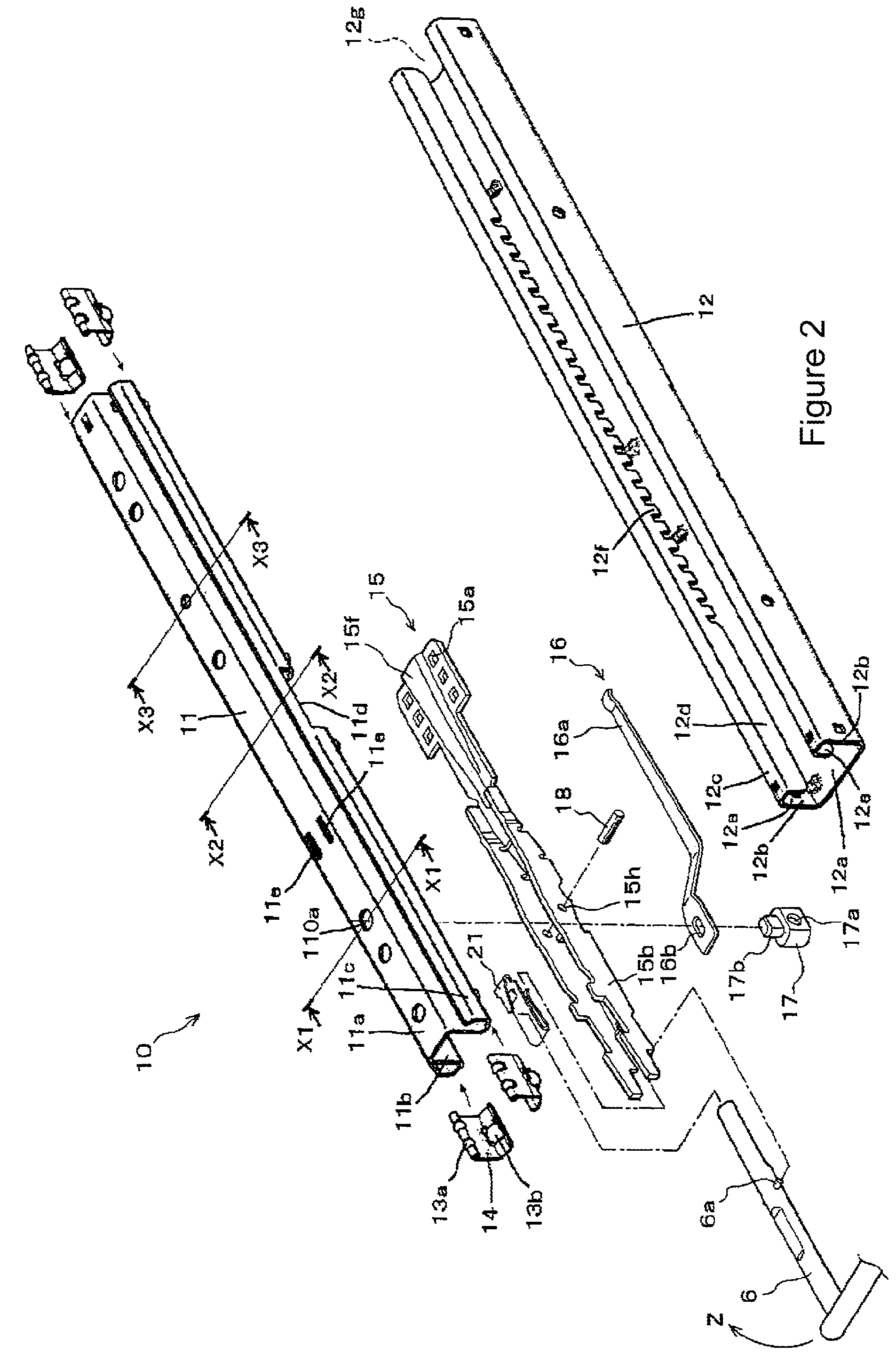
[0044]FIGS. 1 to 7 illustrate the slide rail unit 100 according to an example. FIG. 1 is a side view of the slide rail unit 100 according to the example. FIG. 2 is an exploded schematic view of the slide rail unit 100 according to the example. FIG. 3 and FIG. 4 are cross sectional views of the slide rail unit 100 according to the example. FIGS. 5 to 7 illustrate component parts of the slide rail unit 100 according to the example.

[0045]FIG. 1 is a side view illustrating entire structure of the vehicle seat 1 to which the slide rail unit 100 according to the example is attached. The vehicle seat 1 includes a seat cushion 2 and a seat back 3. Below the seat cushion 2, a pair (right and left) of slide rail members 10 is disposed. In FIG. 1, only one of the slide rail members 10 is illustrated.

[0046]On the upper faces of the upper rail members 11 of the slide rail members 10, the seat cushi...


PUM


Abstract

A simple, compact and easy-to-assemble slide rail unit is provided. The slide rail unit reliably restrains right and left rails from sliding even when the right and left rails are installed onto the vehicle floor at an inclination angle different from each other in a longitudinal direction thereof. The slide rail unit includes a slide rail member having an upper rail member and an upper rail member slidably engaged with each other and a lock lever rotatably pivoted to the upper rail member so as to engage with / disengage from an engagement portion formed on the lower rail member. The slide rail unit also includes an operation lever connected to the lock lever within the slide rail member. Between the lock lever and the operation lever, a leaf spring member is disposed for connecting the lock lever and the operation lever therebetween.

Description

FIELD OF THE INVENTION[0001]The invention relates generally to slide rail units provided with lock mechanisms disposed within the right and left rail units for adjusting and fixing seat position of a vehicle in a front-rear direction thereof, particularly to a slide rail unit provided with an operation lever for simultaneously operating the right and left lock mechanisms.DESCRIPTION OF THE RELATED ART[0002]Conventionally, there have been proposed various kinds of slide rail units provided with lock mechanisms within right and left rails and an operation lever bridged therebetween with which the lock mechanisms can be operated simultaneously. When such slide rail units arranged as described above is installed onto a flat vehicle floor, each of the right and left rails can be restrained from sliding, and the position of the vehicle seat can be secured in a front-rear direction.[0003]However, there is a possibility that a small error may be generated during processing the component par...

Claims


Application Information

Patent Timeline
Patent Type & Authority Patents(United States)
IPC IPC(8): B60N2/02
CPCB60N2/0705B60N2/0887B60N2/085B60N2/0818
Inventor SAKAKIBARA, YOSHIHIROKOUMURA, MITSUNAO
Owner IMASEN ELECTRIC IND
Why Eureka
Try Eureka