DC-DC switching converter device

a converter device and dc-dc technology, applied in the direction of dc circuit to reduce harmonics/ripples, ac network circuit arrangements, power conversion systems, etc., can solve the problems of frequency beating phenomena between different converters, noise reduction that has to be suppressed, and additional low frequency interference, etc., to achieve the effect of reducing noise and being easy to implement into the usual converter circui

Active Publication Date: 2010-05-18
DET INT HLDG LTD
View PDF8 Cites 4 Cited by
  • Summary
  • Abstract
  • Description
  • Claims
  • Application Information

AI Technical Summary

Benefits of technology

[0007]It is therefore the object of the invention to create a DC-DC switching converter device pertaining to the technical field initially mentioned, that allows for the reduction of noise in the case of a plurality of DC-DC converters arranged in parallel and sharing a common input bus and EMI filter, the device being cost-efficient and easy to implement into usual converter circuits.

Problems solved by technology

However, the switching operation of the converter creates noise that has to be suppressed in order to avoid electromagnetic interference (EMI) affecting other devices connected to the power converter.
However, this arrangement leads to frequency beating phenomena between different converters sharing the same line input as well as to additional low frequency interferences.
However, synchronization is not easily possible with basic types of switching converters that are widely used for output voltages of several volts and output currents of about 10-60 A, namely the so-called “quarter-brick” or “eighth-brick” converters.
However, the industry standard quarter and eighth-brick formats do not allow for an extra pin available for external frequency synchronization.
Both possibilities are costly and cumbersome.

Method used


Image

  • DC-DC switching converter device
  • DC-DC switching converter device
  • DC-DC switching converter device

Examples


Embodiment Construction

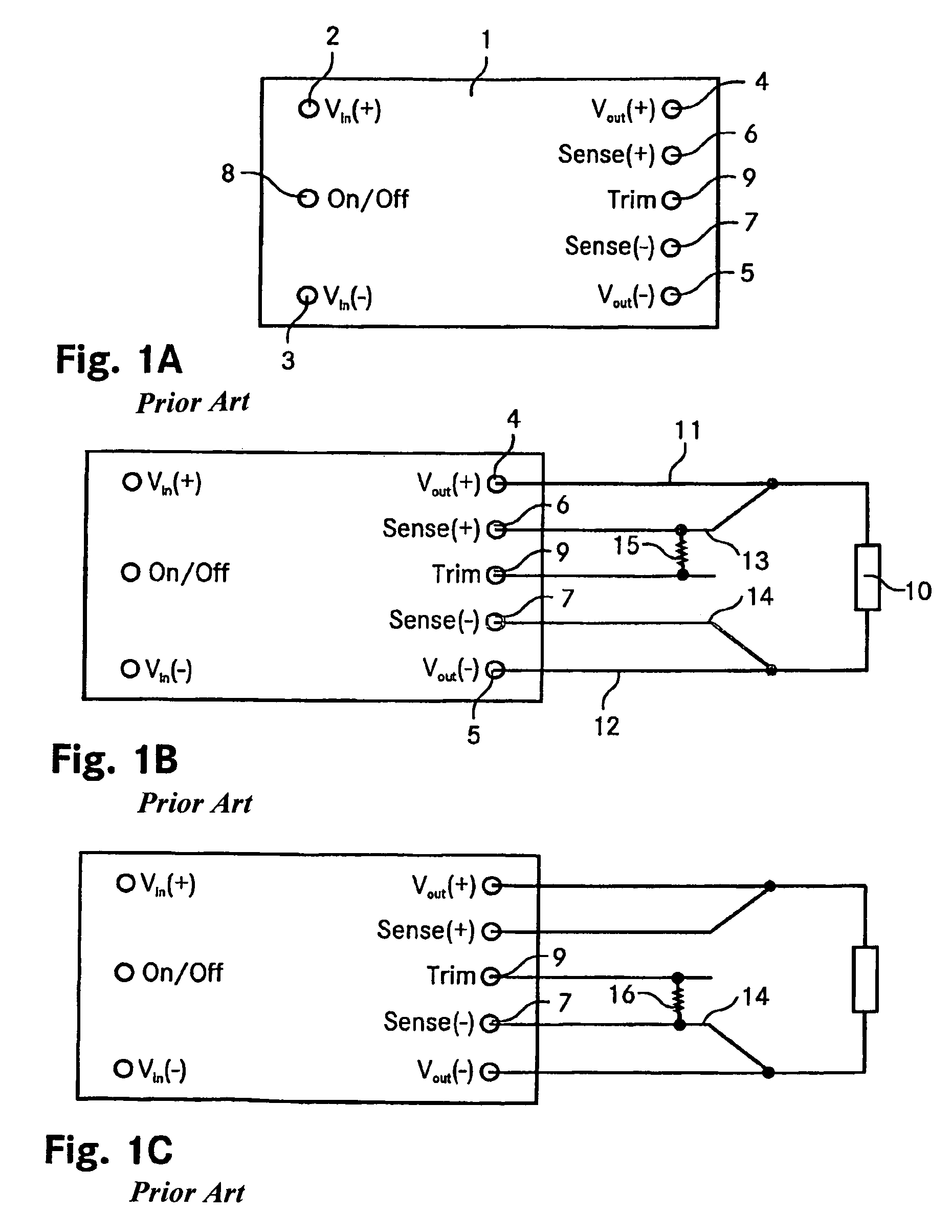
[0042]The FIGS. 1A-C are schematic representations of an industry standard quarter-brick DC-DC converter and of its trim functionality. The FIG. 1A shows the pin out of a standard quarter-brick DC-DC converter 1. It features eight pins, namely two input pins 2, 3 indicated by Vin(+) and Vin(−) respectively, two output pins 4, 5 Vout(+) and Vout(−), two sense pins 6, 7, denoted by Sense(+) and Sense(−), a control pin 8 (On / Off) and finally a trim pin 9 (Trim). The dimensions of a quarter-brick device are 37 mm×58 mm (1.45″×2.3″), its height usually amounts to about 13 mm or less. The pins are on a spacing of 51 mm (2″). The sense pins 6, 7 allow for sensing the line drop and accordingly compensating the output voltage.

[0043]Note, that the invention is as well applicable to eighth-brick DC-DC converters, having the same pin out as described above. Their standard size is 23 mm×58 mm (0.90″×2.3″) with a typical width of about 9 mm. Again, the pins are on a spacing of 51 mm (2″).

[0044]Th...


PUM


Abstract

A DC-DC switching converter device (101), in particular a quarter-brick or eighth-brick device having an industry standard pin out, comprises a pulse-width modulation circuit (132) for driving a power converting switch, a trim connector (109) for adjusting an output voltage of the device, where the device (101) is designed such that the pulse-width modulation circuit (132) is synchronizable to an external oscillator by an external synchronization signal applied to the trim connector. A DC-DC converting circuit comprises a plurality of DC-DC switching converters (101) featuring trim connectors (109) for adjusting output voltages of the converters (101), whereby the converters (101) are connected such that they share a common input bus. It further features a system EMI (electromagnetic interference) filter common to all the DC-DC switching converters (101) and an external oscillator delivering an external synchronization signal to the plurality of DC-DC switching converters (101). The external oscillator is designed such that a frequency of the external synchronization signal is higher than a free running frequency of each of the plurality of DC-DC switching converters (101). The external oscillator is connected to the trim connectors (109) of the DC-DC switching converters (101).

Description

TECHNICAL FIELD[0001]The invention relates to a DC-DC switching converter device, in particular a quarter-brick or eighth-brick device having an industry standard pin out, comprising a pulse-width modulation (PWM) circuit for driving a power converting switch and a trim connector for adjusting an output voltage of the device. The invention further relates to a DC-DC converter circuit and a method of converting a first DC voltage into a second DC voltage.BACKGROUND ART[0002]DC-DC switching converters, i.e. devices that accept a DC input voltage and produce a DC output voltage, in particular on another voltage level, have a wide range of applications in today's power electronics. DC-DC Switching converters are used e.g. for power supplies, DC motor control or battery management. Apart from converting the input DC voltage they provide noise isolation, power bus isolation etc. The switching regulators allow for step-up operation or voltage inversion and offer a higher efficiency compare...

Claims


Application Information

Patent Timeline
Patent Type & Authority Patents(United States)
IPC IPC(8): H02J3/14H02M1/12
CPCH02M1/12H02J1/102
Inventor JITARU, IONEL D.BUCHERU, BOGDAN T.HRISCU, LUCIANDAVILA, JR., MARCO A.
Owner DET INT HLDG LTD
Why Eureka
Try Eureka