Reconfigurable digital logic unit

a digital logic and reconfigurable technology, applied in the field of reconfigurable digital logic units, can solve the problems of large restrictions in the application possibilities of digital logic units of this typ

Inactive Publication Date: 2010-05-18
SIEMENS AG
View PDF13 Cites 7 Cited by
  • Summary
  • Abstract
  • Description
  • Claims
  • Application Information

AI Technical Summary

Benefits of technology

[0015]A further advantage of the logic unit according to the invention can be seen in the fact that the cells of the logic gate have the same read curren...

Problems solved by technology

However, the application possibilities for digital logic units of this type have been greatly restricted heretofore.
One of ...

Method used


Image

  • Reconfigurable digital logic unit
  • Reconfigurable digital logic unit
  • Reconfigurable digital logic unit

Examples


Embodiment Construction

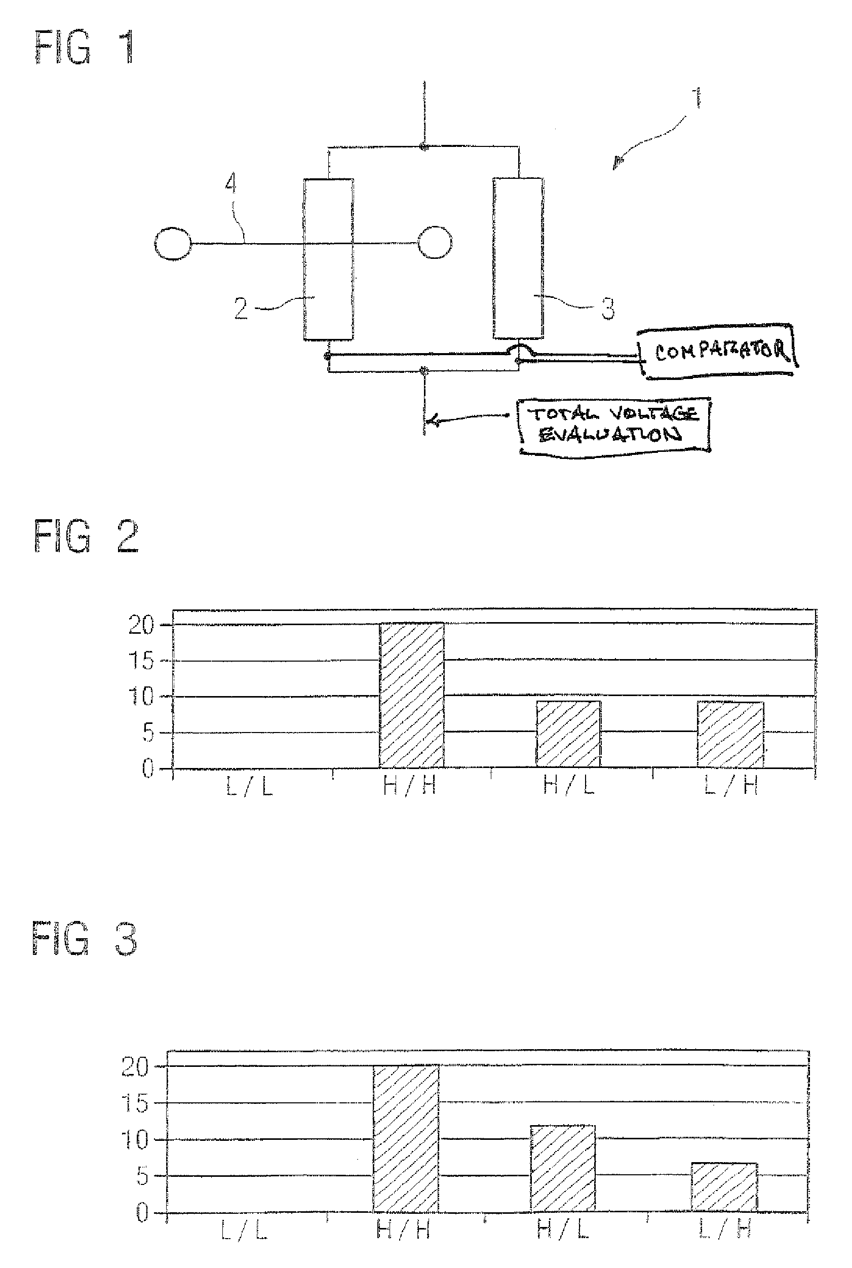
[0026]The logic unit 1 shown in FIG. 1 comprises a data cell 2 and a reference cell 3 connected in parallel therewith. The cells 2, 3 each have a magnetic layer system whose magnetization can be changed over between two states by means of an applied magnetic field. The two states can be interpreted as an information bit and represent the logic states 0 and 1 or low and high. The magnetoresistance changes depending on these states in the percentage range, so that the resistance change can be used for reading out items of information stored in the cell.

[0027]The data cell 2 can be programmed by means of a magnetic field pulse applied to the input line 4. The programmed cell 3 may be either reprogrammable or a constant reference cell. The programming is maintained in nonvolatile fashion and determines the functions of the logic gate.

[0028]The two cells can be changed over from their minimum resistance R1 and R2, respectively, to a higher resistance value by the TMR signal swing m. This...


PUM


Abstract

The invention relates to a reconfigurable digital logic unit comprising at least one logic gate with a cell presenting a magnetic layer system, the resistance of which may be altered by means of magnetic field pulses. Said logic gate comprises at least one first leg with at least one data cell and a second leg, wired parallel to the above, with at least one reference cell and a means for determination of the resistances of the first and second legs, representing a measure of the logical state of the logic gate, whereby the first leg comprises at least two parallel data cells (2).

Description

CROSS-REFERENCE TO RELATED APPLICATIONS[0001]This application is a 371 of PCT / EP05 / 51000.BACKGROUND OF THE INVENTION[0002]The invention relates to a reconfigurable digital logic unit comprising at least one logic gate with cells which have a magnetic layer system and the resistance of which can be altered by means of magnetic field pulses, which logic gate comprises at least one first line branch with at least one data cell and a second line branch—connected in parallel therewith—with at least one reference cell, and also a means for evaluating the resistances of the first and second line branches, said resistances representing a measure of the logic state of the logic gate.[0003]Cells of this type make it possible to store items of information on a magnetic basis. The magnetization of a layer of the magnetic layer system can be changed by means of a magnetic field pulse, so that the magnetoresistance of this layer structure changes by a few per cent. The respective resistance can b...

Claims


Application Information

Patent Timeline
IPC IPC(8): G11C11/00H03K19/00H03K19/18
CPCH03K19/18
Inventor BANGERT, JOACHIM
Owner SIEMENS AG
Why Eureka
Try Eureka