Valve for controlling the flow of fluids

a valve and fluid flow technology, applied in the direction of valve operating means/release devices, liquid transfer devices, transportation and packaging, etc., can solve the problems of increasing the cost of manufacturing valve assemblies, affecting the quality of valves, and affecting the flow of fluids, etc., to achieve simple assembly, simple production, and simple use

Active Publication Date: 2010-05-25
LB EURO
View PDF24 Cites 25 Cited by
  • Summary
  • Abstract
  • Description
  • Claims
  • Application Information

AI Technical Summary

Benefits of technology

[0011]Thus, one object of the present invention is, therefore, to provide a valve assembly which is reliable, relatively inexpensive, easy to manufacture and easy-to-use. It is a further object to provide a valve assembly that includes a tamper evident feature whereby a user can quickly determine whether the valve assembly has been previously actuated or tampered with. Additionally, it is further object to provide a valve assembly that is connected to the container and ready-to-use which cannot be inadvertently actuated during storage or transportation.
[0012]In another embodiment of the present invention, the sealing beads are placed on the sides of the member of the valve assembly so that the sealing beads provide a sealing contact with the inside walls of the tube. It should also be appreciated that the inside walls of the tube could be tapered so, as the member rotatably slides into the closed position, the sealing beads exert a greater force onto the inside walls of the tube providing a tighter seal.
[0013]It should also be appreciated that, in order to prevent accidental actuation of the valve assembly while it is in either the open or closed position, detents can used in conjunction with the protrusions and grooves of the knob.
[0014]It is a further object of the present invention to provide a tamper evident indicator so that a user can quickly see whether the valve assembly was previously opened or tampered with. In one embodiment of the invention, the tamper evident indicator is a skirt that is attached to the knob so that when the valve assembly is first actuated, the skirt can either detach itself from the knob or the skirt can fracture so that the user can quickly determine whether or not the valve assembly has been previously actuated.
[0016]It should also be appreciated that the tamper evident indicators described above can be used to prevent accidental actuation of the valve assembly.
[0017]With all of the above described embodiments of the present invention, the valve assemblies are easy to produce and simple to assemble as the tube and the member can be snap fitted together. Moreover, the valve assemblies of the present invention are simple to use and are relatively inexpensive. And, since all of the valve assembly can be made utilizing plastic the assembly is easily recyclable.

Problems solved by technology

Moreover, since most of the valve assemblies are disposed after use, the cost of manufacturing the valve assemblies is a significant factor.
Some of those prior art valve assemblies generally include relatively complex and involved structures which are difficult to manufacture, such as by molding processes, and / or include fragile elements which are susceptible to breakage.
Such efforts add to the costs of producing such assemblies as well as increasing the complexity of such designs.
It is also a known disadvantage that such valve assemblies with the tap feature have a propensity to open during transportation either because of inadvertent actuation or vibration.
Moreover, all of the prior art valve assemblies present safety concerns.
Neither the assemblies nor containers employ a feature or device to indicate that the containers have been tampered with or that some or all of the fluid has been lost by prior actuation of the valve assemblies.

Method used


Image

  • Valve for controlling the flow of fluids
  • Valve for controlling the flow of fluids
  • Valve for controlling the flow of fluids

Examples


Embodiment Construction

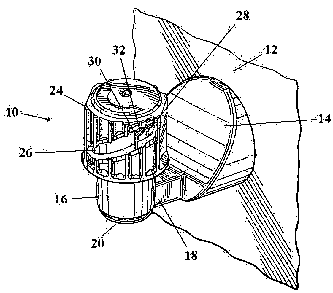
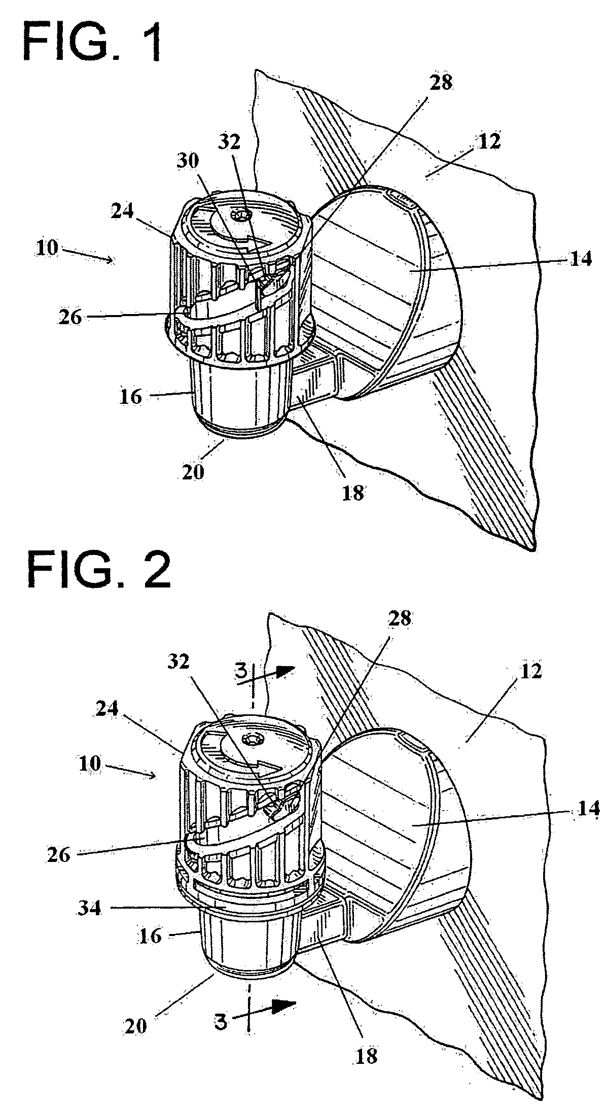
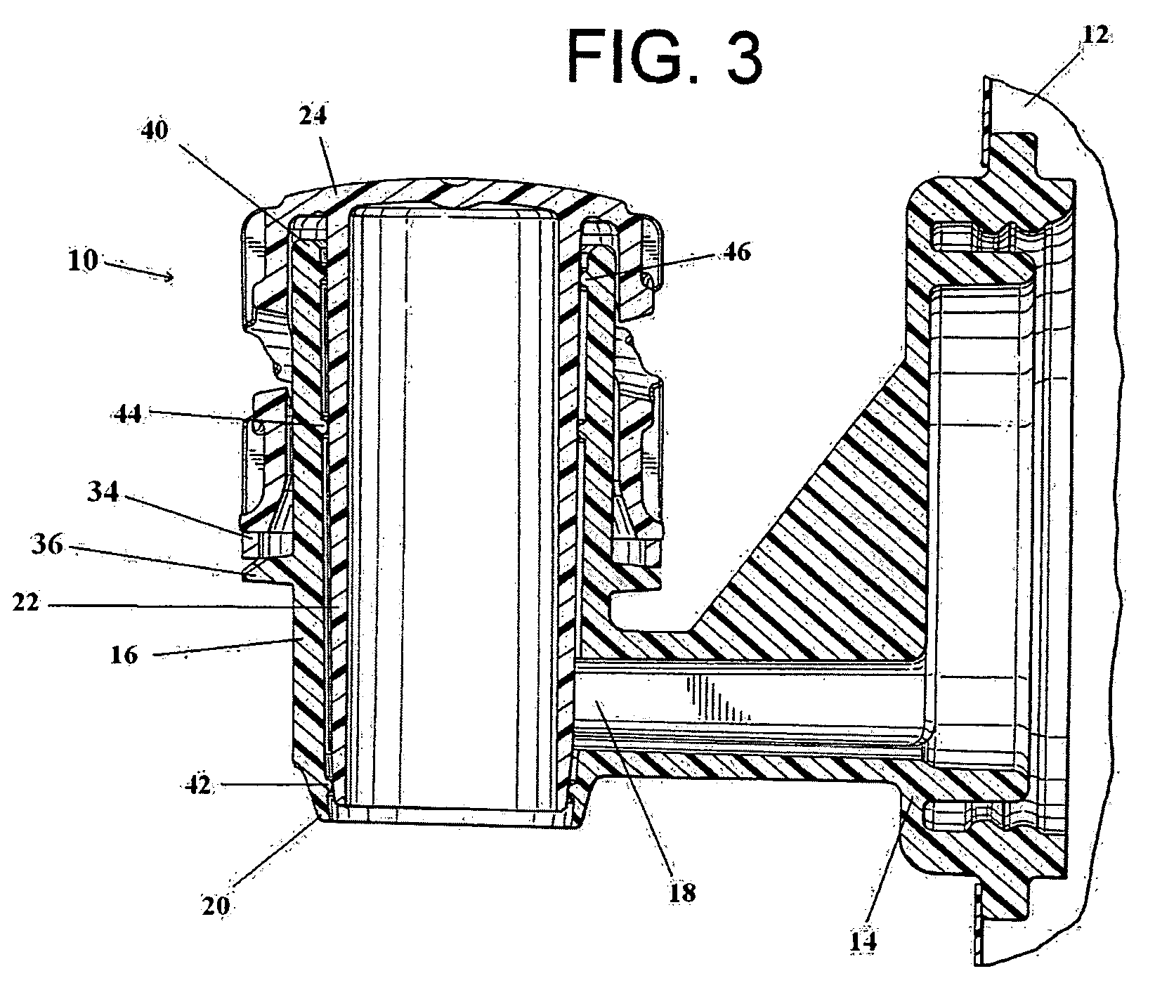
[0025]One embodiment of the valve assembly 10 of the present invention has a configuration as shown in FIG. 1 in which the assembly 10 is already connected to a fluid container 12. In this embodiment the valve assembly 10 is fully assembled and may be attached to the fluid container 12 a number of ways. It may be mechanically attached to a suitable outlet of the fluid container 12 or the valve assembly 10 may be directly attached to the container 12. In the embodiment shown in FIGS. 1 through 4, the valve assembly 10 includes a housing 14 that is sealed to a wall of the fluid container 12. The valve assembly 10 may be made of plastic or other suitable materials.

[0026]The valve assembly 10 also includes an open tube 16 that is connected to the housing 14 by an inlet 18 through which fluid can flow from the container 12. The inlet 18 is connected near a first open end 20 of the tube 14; it is through this first open end that fluid is dispensed from the valve assembly 10. The valve ass...


PUM


Abstract

A valve assembly to dispense fluid from fluid containers including a member that is rotatably slideable in a tube between open and closed positions. The valve assembly utilizes sealing beads to provide seals so that fluid cannot be dispensed from the assembly when the assembly is in the closed position. The valve assembly also includes a tamper evident indicator to show a user whether or not the valve assembly has been previously actuated. The tamper evident indicator may include a tab that is broken when the valve assembly is first actuated. The tamper evident indicator may also include a skirt that either detaches from a knob or fractures when the valve assembly is first actuated.

Description

BACKGROUND OF THE INVENTION[0001]This invention relates to valve assemblies utilized with containers that can control the flow of fluids being dispensed from such containers and specifically valve assemblies having tamper evident devices that show users that the valve assembly has either been previously actuated or tampered with.[0002]Valve assemblies for dispensing fluid from containers, systems or other sources are known in the art. Such valve assemblies, for example, are widely used with containers for dispensing liquids such as wine, syrups, juices, teas and other like beverages. Trouble-free, easy-to-use and reliable valve assemblies are significant considerations in such dispensing applications. Additionally, as valve assemblies are typically disposed of along with their containers once the contained fluid has been consumed, it would be desirable for the valves to be recyclable. Moreover, since most of the valve assemblies are disposed after use, the cost of manufacturing the ...

Claims


Application Information

Patent Timeline
Patent Type & Authority Patents(United States)
IPC IPC(8): F16K3/24F16K35/04
CPCF16K3/246F16K35/04B65D77/067F16K37/0008Y10T137/71
Inventor SMITH, MARK A.RICHARDS, JAMES
Owner LB EURO
Why Eureka
Try Eureka