Clutch mechanism for use in power tools

a technology of power tools and eccentricities, applied in the direction of slip coupling, mechanical control devices, instruments, etc., can solve the problems of decreasing work efficiency, and achieve the effects of stable adjustment of eccentricity, stable transfer of power, and stable transfer of torqu

Inactive Publication Date: 2010-05-25
POSITEC POWER TOOLS (SUZHOU) CO LTD
View PDF19 Cites 6 Cited by
  • Summary
  • Abstract
  • Description
  • Claims
  • Application Information

AI Technical Summary

Benefits of technology

[0007]Another object of the present invention is to provide a clutch mechanism for use in a power tool to adjust eccentricity which makes the adjusted eccentricity stable and can transfer power stably irrespective of whether the torque increases or not.
[0015]The clutch mechanism of the present invention makes adjusted eccentricity stable and can transfer power stably irrespective of whether torque increases or not. In particular, the clutch mechanism of the present invention permits eccentricity to be adjusted whilst remaining unchanged during use. Torque can be transferred stably and working efficiency is improved.

Problems solved by technology

However when the torque exceeds a certain level, the detent member slides out of the detent recess which causes the transfer to fail and the eccentricity to change thereby decreasing work efficiency.

Method used


Image

  • Clutch mechanism for use in power tools
  • Clutch mechanism for use in power tools
  • Clutch mechanism for use in power tools

Examples


first embodiment

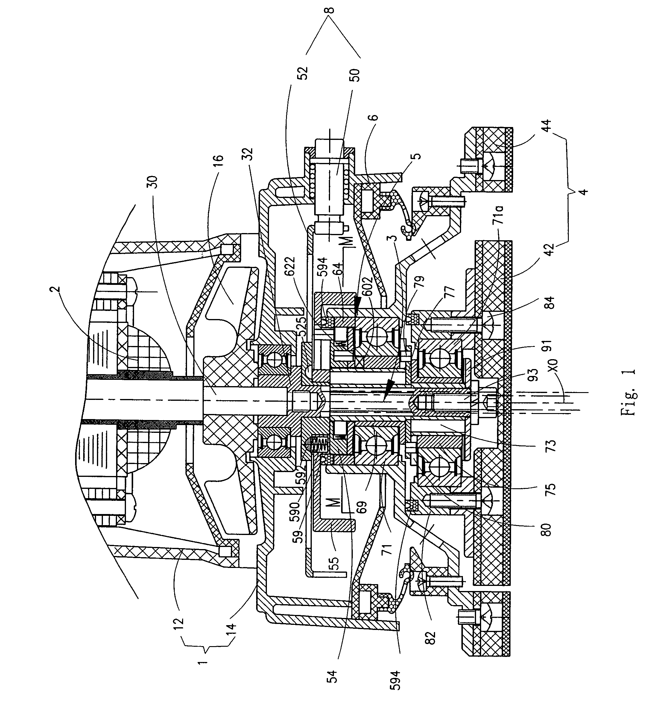
[0062]Referring to FIG. 1, the present invention is a rotary sander. The sander comprises generally a housing 1, a motor 2 vertically disposed inside the housing 1, a principle drive shaft 3, a sanding plate 4 at the base of the housing and an eccentric stroke adjusting mechanism 5.

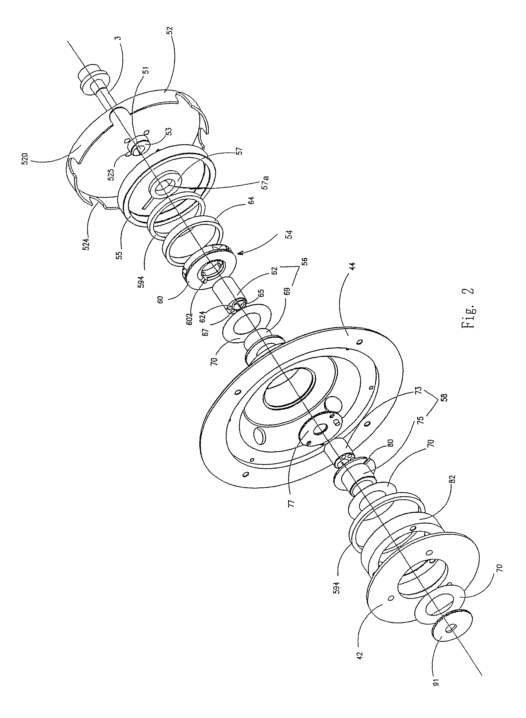
[0063]Referring to FIGS. 2 to 5, the housing 1 comprises an upper housing part 12 and a lower housing part 14 securely connected to each other. A fan 16 is securely attached to the principle drive shaft 3. The principle drive shaft 3 comprises an armature shaft 30 and a connecting shaft 32 connected to the lower end of the armature shaft 30. The connecting shaft 32 and the armature shaft 30 have a common axis X0. The connecting shaft 32 has an irregular cross-section. The sanding plate 4 has an annular inner plate 42 and an annular outer plate 44. A braking system 6 is disposed between the lower housing part 14 and the annular outer plate 44.

[0064]The eccentric stroke adjusting mechanism 5 comprises a pri...

second embodiment

[0080]The operating body 84 of the coupling member 77′ can be manually rotated to allow the eccentric stroke of the sanding plates 46 and 48 to be adjusted. The principle of adjustment is the same as described above for the first and the

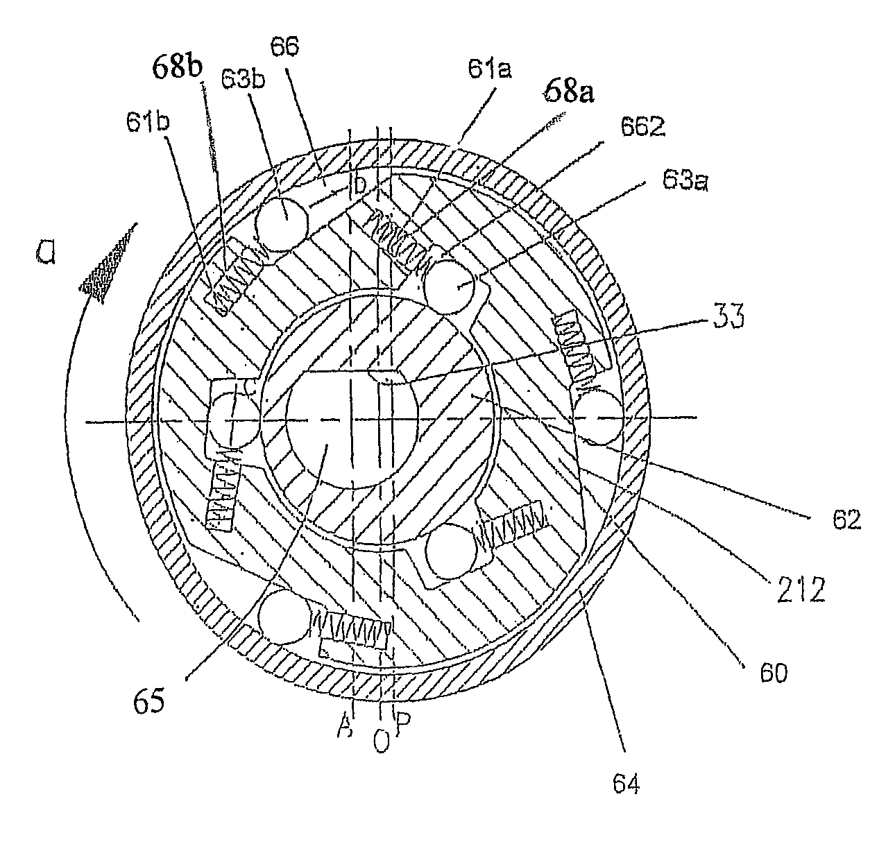
[0081]FIGS. 10 to 12 illustrate in isolation an embodiment of a clutch mechanism 54 of the present invention for adjusting eccentricity in a power tool. The clutch mechanism 54 comprises an annular main body 60 mounted radially on an upper part of an eccentric shaft 62. The annular main body 60 includes a base 60a and a cover 60b. The base 60a has an outer circumferential wall 21, an inner circumferential wall 22 with a central axis Q, a top face 23 and a bottom face. The axis of the outer circumferential wall 21 and the axis Q are eccentric with respect to each other. The base 60a has three axial locating pins 231 at intervals on the top surface 23. The cover 60b has three locating holes 25 formed at intervals. The three pins 231 engage the three ho...


PUM


Abstract

The present invention discloses a clutch mechanism to adjust eccentricity in a power tool. The clutch mechanism comprises an outer race mounted radially on an annular main body which is mounted on an eccentric shaft. At least one first connecting member is disposed between the outer race and the annular main body. At least one second connecting member is disposed between the annular main body and the eccentric shaft. The first connecting member makes the outer race and the annular main body rotate relative to each other at one way. The second connecting member makes the annular main body and the eccentric shaft rotate relative to each other at one way. The annular main body has an axial projection formed thereon to connect with an eccentric mechanism in the power tool. With this type of clutch mechanism, the adjusted eccentricity will not change during working and torque can be transferred stably.

Description

RELATED APPLICATION[0001]This application is a continuation-in-part of U.S. patent application Ser. No. 11 / 346,624, filed Feb. 2, 2006 now U.S. Pat. No. 7,530,881 and entitled “ECCENTRIC STROKE ADJUSTING MECHANISM,” which is incorporated herein by reference.BACKGROUND[0002]1. Field of the Invention[0003]The present invention relates to a clutch mechanism for use in a power tool.[0004]2. Background Art[0005]EP-A-820838 discloses a clutch mechanism for use in a power tool to adjust eccentricity. The clutch mechanism is used to connect a tool head with an eccentric sleeve. The eccentric sleeve can rotate relative to an eccentric fan wheel. A spring-loaded detent member is installed on the eccentric sleeve. A ring member is secured to the eccentric fan wheel and has at least two detent recesses formed thereon. To adjust eccentricity, the tool head is turned and the eccentric sleeve turns which makes the spring-loaded detent member engage different detent recesses on the ring member. Spr...

Claims


Application Information

Patent Timeline
Patent Type & Authority Patents(United States)
IPC IPC(8): B24B23/03F16D41/066
CPCF16D7/10F16D41/073Y10T74/2114
Inventor ZHONG, CHEN CHENG
Owner POSITEC POWER TOOLS (SUZHOU) CO LTD
Why Eureka
Try Eureka